DIY - Heater unit rebuild

My pay back to the forum; here's my approach to rebuilding the heater box from my E9. Not sure how this compares to e3, but let me know and I can possibly merge.

I'll likely chop it in roughly three pieces; removal, disassembly, repair and rebuild. I haven't installed it yet myself, so i can't do any pics of that :) .
I will add sections in the coming days, depending on how boring my meetings in the office will be....

Cost & time estimation: About 450 euro and 30 hours.

- Re-cored heat exchanger: 231 euro
- Re-zinced parts (done with other parts, so I just take a part of it: ) 30 euro's
- 1 square meter of closed cell EPDM foam 5 mm thick with glue backing: 60 euro's
- blacking fluids to recoat the black steel spring wires of the front air vents: 25 euro for a set, but used only 25% of it: 6 euro.
- a few rivets, rattle can black paint, solvent; glue for textile part inside the air duct: say 10 euro's in total.

time consumption: 30 hours; this includes disassembly, making it all fresh again, drop & pick up of the parts of for fresh zinc and recore, an re-assembly. Oh, and a bunch of photo's in between to insure myself for premature Alzheimer...

This will get you:
1. peace of mind that your core doesn't leak. Especially helpful if you don't want to disassemble half of your dash after finishing that 10 years restoration.
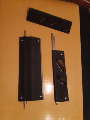
2. A nice and shiny center stack, with air vents that give max air volume output (sometimes blocked by sagging textile inside the air ducts)
3. smooth running fan with no noise from 45 year of gunk /leaves inside etc
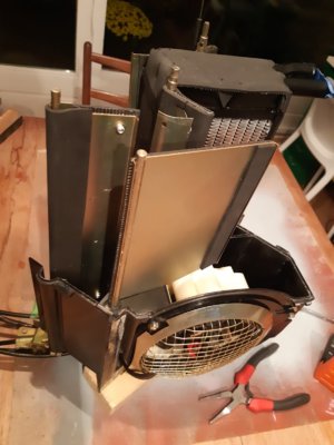
Disassembly:
Getting the heater box out from the dash is difficult. It's quite some work, as it requires you to remove some parts surrounding it to give access to the screws holding it place.
If i remember well, you need to get the glovebox out, and the panel under the steering column. Besides that, you need to remove the center console sides. I don't think you can leave any one of those installed. Also you need to disconnect the water hoses from inside the engine compartment.

20200526_231723.jpg


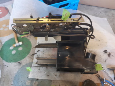
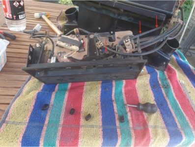
Unscrew bolts from the side of the front panel, they should have 2 left, 2 on right side; see the ratchet position.
20200526_232213.jpg


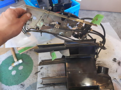
The front panel is now hanging by the control wires and its electrical connector. You can see also the rectangular air duct now comes out (bottom right of photo). My heater unit only had 3 screws instead of the 4 needed...

20200526_232536.jpg


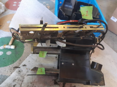
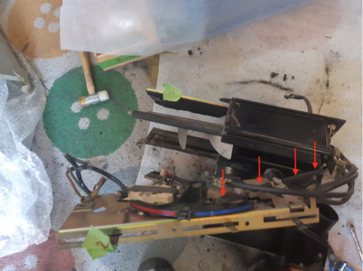
Next step is detaching the unit itself from the firewall. The unit has on either side a large yellow zinced bracket with 4 nuts. (see green lines in image below) Detach those 4 nuts.
20200526_235654.jpg


You now have it loose.

20200531_130435.jpg
 
Last edited:

eriknetherlands

Moderator
Site Donor
Messages
2,698
Reaction score
1,929
Location
Netherlands, Eindhoven area
Disassembly step.
I am one of those guys that simply tear down stuff until the last tiny bits; really enjoy that process, trying to crawl into the mind of the person who designed it: Why did they do it like this? Where is this thing for? It is perhaps what I like the most.

Before starting the disassembly, I felt it was important to document how the rigid cables (rod? wires?) are connected between the controls and the heater unit. The setting of these cables will affect the movement of the internal flaps. If the rigid cables are incorrectly attached later on, your flaps won't be fully closed although the slide control shows you so.

For this I measured how much mm's the rigid cables stick out from their clamping element + I marked them with a red marker. Mind you; this is how it was installed in my car; the controls functioned perfectly, and I think it has never been touched before. The actual setting could possibly, but not likely, be different in your car.
Here they are in case you have already disassembled them without making measurements; you can use mine a basic setting.

There are 4 rigid cables. Each of them connects to one or two flaps. I have identified the cables as 1/2/3/4.

Number 1 is the top middle slide control ( "Kalt-Warm - "Hot & Cold Blue & Red) it attaches to the flap in the middle of the box.​
Number 2 is the bottom left slide control ( "Zu-Luft-Lufter") and controls the amount of air flow. It attaches to the half flap in the top of the box.​
Number 3 is the bottom middle slide control (= "Unten-Oben") : Bottom-Top ). It attaches to the bottom rear of the unit where it direct airflow to your feet or to the window defrosters in your upper dash.​
Number 4 is the bottom right slide control, in my car ("Zu-Luft"). It attaches to the top flap on the heater unit.​

Number 1; Hot-Cold; stick out on first lever is 7 mm. In the third pic you see it also links via the axle of the flap to a rigid pin which connects to another flap at the bottom of the box: I later defined them as 1A (top lever& flap) and 1B (bottom lever & flap). This way you also know which flaps belong behind which lever.
20200601_165754.jpg

20200601_215504.jpg
20200601_162204.jpg

1A and 1B (Hot-Cold cable) attaches to two flaps identified in the pic below as !a and 1B, In the pic the cable is already disconnected from lever 1A.
20200601_220218.jpg


Number 2 (air flow amount) operates the half flap at the top of the box, close tot where the electric cable enters the box for the fan.

20200601_165506.jpg

stick out is 15 mm :
20200601_162501.jpg


Number 3 operates the flaps directing the air to your feet or the upper dash defrost vents; stick out of the wire at the clamp is 7 mm.
20200601_213816.jpg


20200601_162343.jpg

In this picture you see that the rigid cable 3 also connect through the lever to a wire going through the box to also operate the foot/dash selector flap on the other side.
20200601_214656.jpg

Number 4; the top vent, sticks out 8 mm:
20200601_162416.jpg

same as above, but now marked with red marker to help the correct position during re-assembly.
20201014_233250.jpg


Now that we have know-how it should all go back together, we can continue the disassembly.
Removal of the controls: Push off the knobs from behind with a screwdriver. People that have an original car will see that each metal tabs (lever) has a small black plastic sleeve (rectangular cross section).


20200531_151424.jpg

2 screws detach the air vents with light panel:

20200531_151428.jpg
20200531_151432.jpg

remove the little snap clips that hold the light guide to the air vents by bending them open; push a small screwdriver inside and flip one side of the clip open.

20200531_151829.jpg

Now the light bar is loose: My car has a Swiss origin, so i have German language controls. The lights insert from behind, and allows the letters to be read in the night.

20200531_151847.jpg


this now allows us to clean everything. The light guide is painted plastic, clean with a toothbrush with soap and water. Be careful with solvents as they may remove the black paint.

Continue to disassemble the air vents:
Unclip side clips; first step is a light tap or strong thumb push to unclip them.

20200531_152355.jpg

second step; now unclipped, then still need to move outwards; this is a bit of a struggle. Best way is to push from behind to slide the clip off the axle.
20200531_153039.jpg

final result:

20200531_153308.jpg


Now the airvent slides out of the metal frame:
20200531_153426.jpg


Further disassembly of the air vents. These are usually dirty, and the thin wire springs are sometimes rusted/rusty.
Remove springs with a small screwdriver:

20200531_154239.jpg
20200531_154517.jpg


The air guide has a textile inside layer original from factory. Often it is hanging loose. Some people remove it. I choose to reinstall it. I think it is intended to reduces the chop-chop sound of the air flow, but I'm sure it does more in restricting the airflow then in reducing the sound.

20200531_173223.jpg
 

Attachments

  • 20200601_165406.jpg
    20200601_165406.jpg
    267.2 KB · Views: 187
  • 20200601_165754.jpg
    20200601_165754.jpg
    287.8 KB · Views: 167
  • 20200601_165253.jpg
    20200601_165253.jpg
    280 KB · Views: 182
  • 20200601_165754.jpg
    20200601_165754.jpg
    287.8 KB · Views: 186
Last edited:

eriknetherlands

Moderator
Site Donor
Messages
2,698
Reaction score
1,929
Location
Netherlands, Eindhoven area
Having identified what goes where, you can tear it all apart.
start by removing the pivots and hinges. Do make some pic by your own so that you know which levers go where.
I labelled all my pivots/ hinges with 1A/1B/2/3/4 and put them in separate bags with their respective nuts and rings, prior to re-zincing them.

It works best by placing the unit on a table on it's side, with the cables on the bottom. Supporting the box with a wood block will ensure that it is nicely upright and somewhat stable.
- Undo the C-clamps on the side. Remove the grille and disconnect the motor.
- The electric cable is glued water tight through an opening ; I kept it just like that.
- Then proceed to lift the top half of the housing, taking note of the 2 rings on the axles of flap 1A and 1B.

you'll pull out 5 flaps, i labeled them 1A/1B/2/3/4;
(note size of foam piece 1B should be 5x130x300mm (not 5x100x300)
20200602_235315.jpg


2:
20200602_235701.jpg
20200602_235746.jpg

3:
are the 2 foot flaps; no foam there: Use a screwdriver to push the axle out:


20200601_214945.jpg


flap 4 has a neoprene (diving suit material) foam:
20200602_235803.jpg

foam folds around the axle:
20200602_235817.jpg


drill out rivets; remove & label the parts coming off: rings and cilinders ( 'dopje' means cap, it's the small cilinder on the axle of 1B)
Rivets are 4mm diameter.
20200603_152216.jpg
20200603_153251.jpg
20200603_155201.jpg


I label and photograph all sets, this helps to identify the pars once i get them back in a bucket with a 1000 other nuts and bolts from the zincing company.

20200918_152153.jpg
20200918_152447.jpg
 
Last edited:

eriknetherlands

Moderator
Site Donor
Messages
2,698
Reaction score
1,929
Location
Netherlands, Eindhoven area
The fan with motor is easy to get out: remove the 3 screws to get the protection thing off. This exposes a plastic ring that locates the fan and motor. Disconnect the electrics and lift out. It easy if you do this actually as the first step during your disassembly...
20201013_212751.jpg


Put the white fan in a vice, and remove with a screwdriver the black halves around the motor.
20200603_193242.jpg

the black halves have a snap clip on the sides:
20200603_193329.jpg

Remove the round small black cap; it has small snaps on either side.

20200603_193422.jpg

This allows you to lift out the red part with the brushes. (mind you the motor is still available from Bosch for ~85 euro (info Sept 2021)) .
My brushes were fine, so I only cleaned everything up nicely and lubricated with a drop of thin oil.

20200604_084810.jpg


the motor can be pushed out of the white plastic fan. This allows for easy cleaning of the fan: just soak it in your favorite solvent. The fan also has balancing weights attached to it. If removing them (mine had some rust), then do note their position, helped by the angle values on the white part. Also note that they can be at the top or bottom of a blade.
On my fan were thin and thick clips that act as mass balance. Don't loose 'em or you will get a unbalanced thus noisy fan.


20201014_192953.jpg

20201014_193054.jpg
 

Attachments

  • 20200604_085931.jpg
    20200604_085931.jpg
    201.9 KB · Views: 172

eriknetherlands

Moderator
Site Donor
Messages
2,698
Reaction score
1,929
Location
Netherlands, Eindhoven area
IF your heater core / exchanger looks like this, then it's best to get it recored. Google radiotor shop in your neighboorhood. they desolder it, glass bead blast all the seperate components, made a new custom core (no standard cores available appearently), solder it back together and paint with 2K epoxy.
It cost me 231 euro's to have it retrofitted with a new copper core (upgrade from the steel one that it is originally)
20200601_163017.jpg
20200918_161834.jpg

20200918_230446.jpg


i then gave it a nice black layer for moisture protection:
20200918_230856.jpg

20200919_142803.jpg


20200919_142850.jpg


continued with blacking the steel wire springs of the air vents and the mass balances of the fan:
20201013_233146.jpg
Zinced a bucket of parts:

20201002_163418.jpg
 
Last edited:

eriknetherlands

Moderator
Site Donor
Messages
2,698
Reaction score
1,929
Location
Netherlands, Eindhoven area
With all cleaned, re-zinced and repaired, it is time for assembly.
Others who have done the same exercise have also encountered broken plastic housing. This was remedied by those members by riveting an aluminium plate over the crack, combined with epoxy glue. In my case the housing was OK, so no need for such fixes.
(if anyone has pics of such repairs, just send them in (or link) and I'll add them here.)

Assembly sequence is quite straightforward;
1. flaps into half section of housing
2. attach the link mechanisms
3. assembly of heater vents and control unit
4. install of fan/blower/motor.

Rezinced the flaps & get new foam. EPDM closed cell foam 5mm thick with adhesive backing was chosen. Using my laptop to verify the dimensions to pics with measurements upon removal. EPDM holds up very well in warm and humid conditions; (PU foams like some of the original flaps) disintegrate over a lifetime of 10 years.

20201011_220535.jpg


The foam is held in place originally with rivets+glue. Rivets are 4mm diameter; I've used stainless steel rivets combined with fresh zinced rings.

20201011_220429.jpg

New foam around heater core to prevent air leaking around the core. Less air leak, means more effective airflow through the exchanger. with 5 mm foam, it is snug fit into the housing.
20201011_233316_resized.jpg


Foam part on the seal to the firewall was originally 10 mm. I've just stuck 2 sheets of 5mm on top of each other and then punched 2 holes in it using a half inch water pipe clamping ring.

20201023_220420.jpg
20201023_220425.jpg


Flaps that direct air to feet or window screen; plastic parts cleaned and reassembly with fresh zinced parts.
20201011_225841.jpg


re-glue of textile inside the heater duct (i can understand if people simply leave this out)
20201015_205915.jpg


Assembly fan with motor:
20200604_231534.jpg
20201014_192929.jpg


Assembly then continues.
- Install the 2 small plastic foot flaps.
- Then insert the flaps one at a time, locking them in place by attaching the levers (on the right outer side of the box) before sliding the next flap one in.
- When all 4 flaps are in, then insert the heater core.

Don't forget the 2 little cylinders that ensure correct positioning of the flaps 1A and 1B : (see green encircled below):

20201014_194650.jpg


Next step is the one that has many owners challenged: Each flap is on an axle that needs to go through it's corresponding hole in the other housing half. it means that 4 axles need to be aligned, before the half box can connected with it's other half. Now how to get all 4 aligned at the same time?

The answer is you don't; you align the axles one by one. You start at the top of the box, insert one, close the box just a little to keep the first axle in place, while still allowing you to manipulate the next axle. And you work your way down.

I've used that method and it took me one go and just 3 minutes. This way the gap between the housing halves gets smaller every time on axles slides into place, keeping the already placed axles in their respective slots. I've set the half with the motor on it's side, with a 4cm thick wood block under it to allow for easy manipulation; see pics above and below.

Start by putting the other half housing roughly on top.

20201014_194847.jpg

step 1. Insert this axle first, it is the axle at the top of the box.

20201014_194929.jpg

step 2. (that's why two fingers...) Next axle is this one.
20201014_194933.jpg

3rd step, (3 fingers...)
20201014_194939.jpg

step 4. last axle is the one near the bottom.
20201014_195151.jpg

Close the box up with the "C" clips joining the two housing halves.

Final step is the control unit; all that is left is this Lego work; quite straightforward if you've disassembled it yourself.

20201015_214544.jpg


After this i also made a new seal for the housing to the firewall. It is available from W&N as one piece stamping (link to be inserted later), but as I had the foam material already i made it myself, stacking two layers to give a thickness of 10 mm.

Last thing: check for left over screws....

All Done!

Let me know if you are missing some info or pics. My fully assembled unit is still in an box waiting for installation in a year or 2, so i can make some additional pics if needed.

Update March 2022:
A nice thread documenting how to get it all back in the car with some hints can be found here: Thread 'DIY: Re installing the heater box: ' https://e9coupe.com/forum/threads/diy-re-installing-the-heater-box.40109/
 

Attachments

  • 20201011_220429.jpg
    20201011_220429.jpg
    125.7 KB · Views: 186
  • 20201014_194650.jpg
    20201014_194650.jpg
    214.2 KB · Views: 207
Last edited:

halboyles

Well-Known Member
Site Donor
Messages
659
Reaction score
677
Location
KC
Wonderfully photographed and detailed writeup! Thank you.
 

Blinkling

Well-Known Member
Site Donor
Messages
241
Reaction score
130
Location
San Luis Obispo, CA
This is so nice, having all of these quality photos in one place. The re-zinc'd parts are gorgeous!

I'm interested in the textile piece inside the heater duct. Did you reattach it? Do you suppose it's there in order to reduce the noise coming from the vents?

Thanks for all this!
 

eriknetherlands

Moderator
Site Donor
Messages
2,698
Reaction score
1,929
Location
Netherlands, Eindhoven area
Thanks for all the kind words. Hope it is helpful to someone, just as I find many helpfull things myself here.

I did glue the textile piece back. I thought it would disintegrate during dismantling, but it was quite intact. I gave it a good clean up with washing-up also.

What it does?
Well, first of all it reduces the airflow quite effectively, even if glued tightly to the inside, although I do think the original intention must have been to quiet the system.

Fyi, no single air duct in modern cars have this, so it must have been an "experiment" I think.
Cool, our cars now fall in the 'experimental' category...
 
Last edited:

bavbob

Well-Known Member
Site Donor
Messages
3,354
Reaction score
1,568
Location
Boston, Ma
Awesome. I had to use a smattering of images from a million sites to do this, now all in one place for my next life.
 
Last edited:

bluecoupe30!

Well-Known Member
Site Donor
Messages
2,136
Reaction score
1,283
Location
Delta, British Columbia, Canada
I just recently needed a new Bowden cable and PRDesignsf is all over this. They have been rebuilding 2002 heaters for years and recently branched out into E9s. I needed the cable that runs inside the 'box that switches from demister to heat into cabin. Brendan made a replacement up in no time, with the correct 3 ring loop end. Exact, correct replacement part. Where else can you get this?
 

eriknetherlands

Moderator
Site Donor
Messages
2,698
Reaction score
1,929
Location
Netherlands, Eindhoven area
@eriknetherlands I'm missing this Bowden wire:
Where does it go connected in the heater box?
Tks.

I think what you are missing is cable #1, the hot-cold setting, connecting to lever 1a & Lever 1b. In post 2 above, the first, second and third pic show it's connections on the side of the box.

If you have all other cables, you should have just these 2 levers left 'empty; without actuator'.

Erik.
20200601_162204.jpg
 
Last edited:

Frederick

Well-Known Member
Site Donor $$
Messages
358
Reaction score
276
Location
Park City,UT
Just over the top work on this heater box, thanks for the time and effort. Question, my E3 box ended up with 4 dopji's. Was such a mess I did not even see them . 2 definetly go where you have them but the other's?? No clue
 

eriknetherlands

Moderator
Site Donor
Messages
2,698
Reaction score
1,929
Location
Netherlands, Eindhoven area
@Frederick : I never disassembled an e3 box, so I wouldn't know for sure.

Some guesses and my approach if I had it on my kitchen table today:

Purpose of the 2 "dopjes", (cylinders), is to keep the axle in the right position inside the box: to prevent it from sliding left to right.
It's my guess that if you look at the functionality of your flaps, that you could decipher where they should belong. Assemble the box as you think it should, then push and pull all axles. If one moves by that distance (~4 or 5 mm) or possibly even drops in the box then you found out where you're missing one.


They could theoretically also be located on the outside of the box, but I doubt that as (at least in my e9) the axles on the outside had flat spots to exactly locate the levers to them, so they are needed in my e9 to guarantee the 'depth' or position of the axle there.

Hth, Erik
 
Last edited:

deQuincey

Quousque tandem...?
Site Donor
Messages
8,371
Reaction score
2,389
Location
BIO - 43°15'46.5"N 2°56'03.7"W
Thanks for all the kind words. Hope it is helpful to someone, just as I find many helpfull things myself here.

I did glue the textile piece back. I thought it would disintegrate during dismantling, but it was quite intact. I gave it a good clean up with washing-up also.

What it does?
Well, first of all it reduces the airflow quite effectively, even if glued tightly to the inside, although I do think the original intention must have been to quiet the system.

Fyi, no single air duct in modern cars have this, so it must have been an "experiment" I think.
Cool, our cars now fall in the 'experimental' category...

this is an extraordinary work, Erik
very well done and documented
thank you
 

Fritzie

Active Member
Messages
72
Reaction score
61
Location
The Netherlands
IF your heater core / exchanger looks like this, then it's best to get it recored. Google radiotor shop in your neighboorhood. they desolder it, glass bead blast all the seperate components, made a new custom core (no standard cores available appearently), solder it back together and paint with 2K epoxy.
It cost me 231 euro's to have it retrofitted with a new copper core (upgrade from the steel one that it is originally) View attachment 127215View attachment 127216
View attachment 127217

i then gave it a nice black layer for moisture protection:
View attachment 127218
View attachment 127219

View attachment 127220

continued with blacking the steel wire springs of the air vents and the mass balances of the fan:
View attachment 127221Zinced a bucket of parts:

View attachment 127222
Hello Eric, you did the zinc by yourself (?)
 
Top