how to asses the state of my engine, what to do with it, and how to proceed?

I enjoyed my engine rebuild project very much - and I see it as similar to your goals of having ability to do a lot yourself and farm out the machining expertise etc to others. Since you’ve been burning oil, obviously the head needs rebuilding (and possibly rings also) and opportunity for a 284 cam.

This is also an opportunity to upgrade the block with a cylinder hone/bore and high compression pistons. I had mine bored for 10:1 pistons, crankshaft polished, rotating assembly weighed and then all assembled into the block. I did the rest of the assembly.

Then you would likely get your 180hp goal.

Disassembly is quick and easy, assembly requires care and concentration but is immensely rewarding.
Stevehose, I read with interest that you upgraded your pistons to 10:1. I have my E9 CSL engine apart, and am embarking on a ebore. But I’ve drawn a complete blank with stock oversized pistons. A couple of manufacturers have said they can make custom ones if I can give them a sample of the old piston, but if I go this custom route how do you specify pistons with higher compression?
David
I spoke with Steve Nelson at Topend Performance, he took the specs of my engine (stock M30, later head), what I wanted to achieve, and knew exactly what to order from JE Pistons on my behalf. He's done this many times with M30's. I can send you his email if you'd like.
 
I have an M90 with 10:1 pistons etc and a dogleg. I am running a 284 cam and that is more than plenty.Pistons were ordered from Diamond Racing Pistons, I think they are/may be, a subsidiary of JE. The difference being a much shorter delivery time. The piston info was supplied by the engine builder. You have to know exact specs as to crown height of the piston, bore size and head thickness, New rings and wrist pins should also be included
 
Last edited:
I spoke with Steve Nelson at Topend Performance, he took the specs of my engine (stock M30, later head), what I wanted to achieve, and knew exactly what to order from JE Pistons on my behalf. He's done this many times with M30's. I can send you his email if you'd like.
That would be great if you could put me in touch with Topend Performance. I would like a modest improvement in performance, 220BHP would be nice. I’m struggling to make progress at the moment. Much obliged.
 
That would be great if you could put me in touch with Topend Performance. I would like a modest improvement in performance, 220BHP would be nice. I’m struggling to make progress at the moment. Much obliged.
PM sent to you with info.
 
Before you do ANYTHING, other than remove the engine from the car and put it on an engine stand, DO A LEAKDOWN TEST.

Engines fail/wear in different ways, and unless you plan to totally disassemble and rebuild every part of the engine, you need to assess what specifically, if anything, needs to be addressed.

Consider the basic engine as a mechancal pump. It sucks in air, compresses it, and then pumps out the compressed air. Other than the pressures involved, from a combustion prespective the mechanical components of the engine are not involved. So, let's look at what the mechancis of the engine actaully comprise, assuming that there is no combustion.

Valves: Valves open to let air in, close to allow that air to be compressed, and then open to allow the compressed air out.
Cyliner head: The cylinder head obviosuly serves as the base for the valves, but it, and the gasket, also seals the cylinders from the outside as well as the water jackets, and in some engines the adjacent cylinders.
Rings: The piston rings seal the pistons in the bores, and allow the pistons to compress the air. If the rings or the bores or both are worn, then you will not gain good sustained compression.

So, how can we test these? Turns out it is pretty simple. See the attached slide deck I did about 15 years back. In a nutshell, we use compressed air to pressurize each cylinder in turn. Placing the piston for that cylinder at top dead center (TDC), we apply air at 100 PSI to the cylinder via the plug hole. This air is provided by a valve and gauge arrangement: the valve allows the control of pressurized air through the setup. A pressure gauge on the compressor side, and a pressure gauge on the cylinder side, separated by a small orifice shpws the pressure drop between the compressor side (fixed) and the cylinder being tested. This orifice (usually 0.060" dia) means that if air is flowing, then the pressure will be different on the cylinder side than the compressor side, and that pressure drop is what we are seeking to determine.

I use a compression tester hose that screws into the plug hole to attach this setup to the cylinder.

So with this setup:
  • Set the compressor pressure to 100 psi.
  • Place the piston for the cylinder under test at TDC with the valves closed.
  • Open the air valve. If the crank moves, you were not at TDC, so move the crank a bit until the crank does not move with the valve open.
  • If the pressure on the compressor side is 100, you should see some pressure below 100 on the cylinder side. Measure and record the pressure on the cylinder side gauge.
  • Using a small plastic hose, determine where any air leakage is coming from. This may be: Intake manifold, exhaust manifold, coolant (bubbles in radiator), or crankcase (air coming fromthe dip-stick tube), or an adjacent cylinder (determined by air is coming out of the adjacent cyliner plug hole). Record this.
  • Repeat this for each cylinder.

If you have a cylinder with bad exahaust valves, the leakage will be into the exhaust manifold. If it is intake valves, then the air will be going into the intake manifold. If it is cylinder to cylinder, then you can determine this by listening for air from the adjacent cylinder plug holes. If it is rings or bores, then you will have air coming out of the dip stick tube. If you have a bad gasket, then you will find air bubbles in the coolant reservoir.

In addition, the pressure gauges will give a relative leakage number in percent from the base 100 PSI. That part is sort of like a conventional compression test, except now you know where the compression is being lost.

As described in the PDF, some engines just need head work (e.g valves). Others have bad rings or bores, and some just need a new head gasket. Some need multiple of these.

The bottom ends of these engines are generally very solid, so it is possible, but somwwhat unlikely, that you may also need bottom end bearings, and/or new pistons. Some guys rebuld everything on principle. But if you just want a solid engine without a total rebuild, let the leak test guide you.
 

Attachments

  • Leakdown Test.pdf
    175.6 KB · Views: 10
I was going to dyno it but new job/long commute and a wood boat have lowerd my desire to do so. Maybe one day.
Curious, what is your wood boat? I restored a 1929 Stephens Cruiser back in 2012...
 

Attachments

  • WB Cover.jpg
    WB Cover.jpg
    213.2 KB · Views: 16
Before you do ANYTHING, other than remove the engine from the car and put it on an engine stand, DO A LEAKDOWN TEST.

Engines fail/wear in different ways, and unless you plan to totally disassemble and rebuild every part of the engine, you need to assess what specifically, if anything, needs to be addressed.

Consider the basic engine as a mechancal pump. It sucks in air, compresses it, and then pumps out the compressed air. Other than the pressures involved, from a combustion prespective the mechanical components of the engine are not involved. So, let's look at what the mechancis of the engine actaully comprise, assuming that there is no combustion.

Valves: Valves open to let air in, close to allow that air to be compressed, and then open to allow the compressed air out.
Cyliner head: The cylinder head obviosuly serves as the base for the valves, but it, and the gasket, also seals the cylinders from the outside as well as the water jackets, and in some engines the adjacent cylinders.
Rings: The piston rings seal the pistons in the bores, and allow the pistons to compress the air. If the rings or the bores or both are worn, then you will not gain good sustained compression.

So, how can we test these? Turns out it is pretty simple. See the attached slide deck I did about 15 years back. In a nutshell, we use compressed air to pressurize each cylinder in turn. Placing the piston for that cylinder at top dead center (TDC), we apply air at 100 PSI to the cylinder via the plug hole. This air is provided by a valve and gauge arrangement: the valve allows the control of pressurized air through the setup. A pressure gauge on the compressor side, and a pressure gauge on the cylinder side, separated by a small orifice shpws the pressure drop between the compressor side (fixed) and the cylinder being tested. This orifice (usually 0.060" dia) means that if air is flowing, then the pressure will be different on the cylinder side than the compressor side, and that pressure drop is what we are seeking to determine.

I use a compression tester hose that screws into the plug hole to attach this setup to the cylinder.

So with this setup:
  • Set the compressor pressure to 100 psi.
  • Place the piston for the cylinder under test at TDC with the valves closed.
  • Open the air valve. If the crank moves, you were not at TDC, so move the crank a bit until the crank does not move with the valve open.
  • If the pressure on the compressor side is 100, you should see some pressure below 100 on the cylinder side. Measure and record the pressure on the cylinder side gauge.
  • Using a small plastic hose, determine where any air leakage is coming from. This may be: Intake manifold, exhaust manifold, coolant (bubbles in radiator), or crankcase (air coming fromthe dip-stick tube), or an adjacent cylinder (determined by air is coming out of the adjacent cyliner plug hole). Record this.
  • Repeat this for each cylinder.

If you have a cylinder with bad exahaust valves, the leakage will be into the exhaust manifold. If it is intake valves, then the air will be going into the intake manifold. If it is cylinder to cylinder, then you can determine this by listening for air from the adjacent cylinder plug holes. If it is rings or bores, then you will have air coming out of the dip stick tube. If you have a bad gasket, then you will find air bubbles in the coolant reservoir.

In addition, the pressure gauges will give a relative leakage number in percent from the base 100 PSI. That part is sort of like a conventional compression test, except now you know where the compression is being lost.

As described in the PDF, some engines just need head work (e.g valves). Others have bad rings or bores, and some just need a new head gasket. Some need multiple of these.

The bottom ends of these engines are generally very solid, so it is possible, but somwwhat unlikely, that you may also need bottom end bearings, and/or new pistons. Some guys rebuld everything on principle. But if you just want a solid engine without a total rebuild, let the leak test guide you.
Thanks. Appreciated. David
 
Curious, what is your wood boat? I restored a 1929 Stephens Cruiser back in 2012...
Wow that's amazing - stunning. Wood work is out of my league but I have immersed myself in sorting everything mechanically on mine with Thanksgiving as sea trial target date:

 
Wow that's amazing - stunning. Wood work is out of my league but I have immersed myself in sorting everything mechanically on mine with Thanksgiving as sea trial target date:

Sweet boat!! You should probably read "Brightwork" by Rebecca Wittman. Lots of varnish work in your future!!! I use Epifanes, with a foam brush. Never could get a good finish with bristles..

You can see my resto blog at Wooden Boat Forum

The interior came out especially nice...
 

Attachments

  • 20130202_R7X2942.jpg
    20130202_R7X2942.jpg
    480.7 KB · Views: 12
Last edited:
A few questions about leakdown test have always eluded me:

1) Isn't it important to measure leakdown when piston is at 3 or more levels through the bore? Because outside of strong leakage through a valve or head gasket, the condition of the bore/ring seal along the entire displacement (blowby) is important. Known valve or head gasket leakage probably overshadows any ring leakage, no? Maybe the greatest wear is at TDC where ignition happens?

2) How would the best orifice size be determined? I imagine the measured pressure drop would be dependent on the ratio of the leakage to the orifice size. With an adjustable orifice, one could tune to the maximum pressure drop and use that number.

3) is squirting oil / re-testing / verifying rings still a valid method?

I did some leakdown testing and motor work decades ago but have a few projects around here that need it now.
 
SKK PM sent. I think we know one another from my Silicon Valley days.

1) Measuring the leakage at different piston positions during the compression stroke might be useful. It is rather difficult though. In my experience, you can gain a great deal of respect for the torque of an engine based on how hard the crank moves if the piston is not at TDC during the leak test.Usually you have a breaker bar on the crank nut to turn the crank as you fnd TDC.. If you open the valve too fast, and the piston is not at TDC it can nearly break your arm! So holding the crank with the piston at some intermediate position would be a challenge.

2) Great question. I agree that the rate of leakage would determine the flow through the orifice and thus the pressure drop. So in the extreme, with no leakage, any size orifice would work, since the pressure will be the same on either side. At the other extreme, if we assume total leakage, then we would adjust the orifice to give us zero gauge pressure on one side and 100 PSI on the other. Obviously in this case, the larger the orifice the harder it will be to maintain pressure on the compressor side. a larger flow rate compressor would support a larger orifice and thus greater amounts of leakage

In practice though, the test is not quite that absolute. You are hoping for very low levels of leakage, so if you have high leakage, the degreee is not really that important, but where it is leaking is (because that's what youare going to need to fix). Valves that leak at 30% need to be replaced the same as valves that leak at 60%, same with rings..

So the 0.060" rule of thumb seems to work. Might be interesting to experiement with it though. When I made my leak test setup I used a 1/4" NPT nipple about 1 inch long between two brass T's, one for each gauge. I filled the nipple with JB Weld, and then drilled a hole in it. You could probably start with a rather small hole, and keep increasing it until you start to get a drop onthe compressor side, and then back-up one size.

3) Some folks may disagree with me, but the oil test seems more useful in a conventional compression test. Adding oil in that test can improve the ring seal, and thereby allow you to differentiate between ring leakage and valve leakage. If you have low compression in that test, then if the loss is a result of rings, then adding oil shoudl improve the compression, whereas adding oil will not change the loss due to valve leakage. In a leak test, you are already differentiating between ring and valve leakage, so the oil is less informative. It might confirm that the leakage is rings, but you would have already determined that with a dry bore.


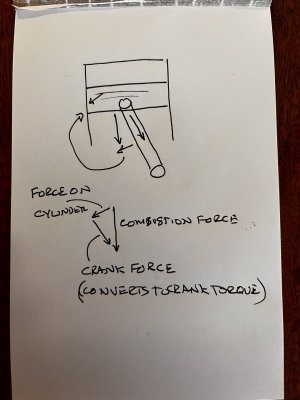
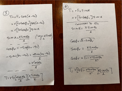
As an aside, TDC is where the greatest cylinder pressure is, so that's where leakge will be most pronounced, and have a greatest impact. I suspect the greatest piston/ring/bore wear wil occur farther down the bore. As the piston moves down, the connecting rod is applying force to the crank at an increasing angle relative to the top of the piston, thus a portion of the combustion force is directed to the crank, and a portion will be directed to the side of the piston, and this will be resisted by the cylinder wall. So the farther down the bore the piston is, the more the force on the connecting rod will be applied to the cyliner wall. Of course the cylinder gas is expanding, and the piston movement is increasing the cylinder volume, so the magnitudes of these forces are changing as the piston moves. There is probably some point in the vertical trajectory of the piston where the side load on the piston is the greatest, and that's where the bore wear will be the greatest. Seems that longer stroke engines will see greater side loads than shorter stroke engines. See attached pic. I'll bet there are some cool models of this dynamic behavior. Sounds like a good Matlab problem!!
 

Attachments

  • IMG_3177.jpg
    IMG_3177.jpg
    268.4 KB · Views: 5
Last edited:
Back
Top