Hi everyone,
In the past, I've had to replace the squirrel cage blower fan on my AC console twice as the bearings have gone bad. Replacement fans are difficult to come by and this had me thinking about finding a replacement fan/motor. It turns out that fan assemblies the size of ours are used in tractors. Some are 12V, some are 24V.
I believe that for a optimally set up AC system, an increased volume of air across the evaporator will yield the most benefit. We can routinely get outlet air temperatures in the mid-30's, and in fact, even freeze the evaporator. Based on this, I set up to measure if there would be an improvement in using a 24 V fan, and investigate how to set it up.
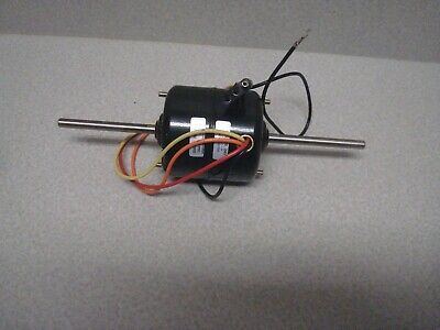
Here's the Caterpillar 24 Volt blower fan. This version came with plastic fans but the Behr/Bosch metal fans can be retrofitted. The only modification needed to fit the assembly is to slide one of the plastic fans further inboard.


You'll notice the fan has 4 wires. This is because it has built-in resistors to vary the speed. What this means is that we can ditch the problem-prone switch and go to a simple 3 speed fan switch as seen below, next to the original switch. This switch is easier to fit and one more weak link in the system is removed. The replacement switch is Four Seasons 35702

In order to run the fan a step-up converter is necessary. These things have gotten very cheap, small and efficient in recent years. This is one is very small, >95% efficient and consumes under 10 milliamps when idle, which is negligible. Full specs here: https://www.daygreen.com/products/12v-to-24v-10a-240w-dc-dc-step-up-converter-voltage-regulator


So how much more air volume does it provide? I ran a test set up with a loaner evaporator box courtesy of Stevehose (thanks!) and measured wind speeds and given the air outlet area teh anemometer calculates the volume in CFM. The voltage was around 13.4 volts from a running (modern)vehicle alternator so current supply was not a limiting factor.
I found it most meaningful to measure the airflow into the unit, left and right. Interestingly, the air draw is not symmetric, it pulls more air from the right side.
The average measurement with the Bosch fan on the left side was 340 CFM and with the Cat, 390. On the right side, 367 CFM Bosch, Cat, 420. So an improvement of nearly 15%. Since this is air volume, I think it's pretty significant. An automotive HVAC expert on Quora claims 1,100-1,500 CFM is what modern auto ACs provide. Besides the improvement, it helps me lose the difficult-to-source Bosch fan and fan switch.


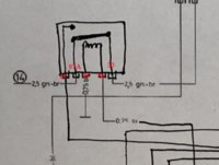
Blow is the stock wiring diagram for this section of the car and the modifications needed to incorporate this. I have not yet implemented this as I have zero desire to pull the console for a 3rd time but I see no reason why it wouldn't work, but please feel free to critique.
Essentially the 24V converter intercepts the 12V supply it feeds the new switch, which is wired with each of the speeds/colors coming from the fan motor. Each of the 3 ON positions on the switch also feeds a new 24V relay (with 87 and 87a [normally closed] output terminals) which then shuts down the heating system blower fan and sends 12V power to the thermostat switch and onwards to the AC compressor clutch and condenser fan relay.
Stock:

Modified:

In the past, I've had to replace the squirrel cage blower fan on my AC console twice as the bearings have gone bad. Replacement fans are difficult to come by and this had me thinking about finding a replacement fan/motor. It turns out that fan assemblies the size of ours are used in tractors. Some are 12V, some are 24V.
I believe that for a optimally set up AC system, an increased volume of air across the evaporator will yield the most benefit. We can routinely get outlet air temperatures in the mid-30's, and in fact, even freeze the evaporator. Based on this, I set up to measure if there would be an improvement in using a 24 V fan, and investigate how to set it up.
Here's the Caterpillar 24 Volt blower fan. This version came with plastic fans but the Behr/Bosch metal fans can be retrofitted. The only modification needed to fit the assembly is to slide one of the plastic fans further inboard.
You'll notice the fan has 4 wires. This is because it has built-in resistors to vary the speed. What this means is that we can ditch the problem-prone switch and go to a simple 3 speed fan switch as seen below, next to the original switch. This switch is easier to fit and one more weak link in the system is removed. The replacement switch is Four Seasons 35702
In order to run the fan a step-up converter is necessary. These things have gotten very cheap, small and efficient in recent years. This is one is very small, >95% efficient and consumes under 10 milliamps when idle, which is negligible. Full specs here: https://www.daygreen.com/products/12v-to-24v-10a-240w-dc-dc-step-up-converter-voltage-regulator
So how much more air volume does it provide? I ran a test set up with a loaner evaporator box courtesy of Stevehose (thanks!) and measured wind speeds and given the air outlet area teh anemometer calculates the volume in CFM. The voltage was around 13.4 volts from a running (modern)vehicle alternator so current supply was not a limiting factor.
I found it most meaningful to measure the airflow into the unit, left and right. Interestingly, the air draw is not symmetric, it pulls more air from the right side.
The average measurement with the Bosch fan on the left side was 340 CFM and with the Cat, 390. On the right side, 367 CFM Bosch, Cat, 420. So an improvement of nearly 15%. Since this is air volume, I think it's pretty significant. An automotive HVAC expert on Quora claims 1,100-1,500 CFM is what modern auto ACs provide. Besides the improvement, it helps me lose the difficult-to-source Bosch fan and fan switch.
Blow is the stock wiring diagram for this section of the car and the modifications needed to incorporate this. I have not yet implemented this as I have zero desire to pull the console for a 3rd time but I see no reason why it wouldn't work, but please feel free to critique.
Essentially the 24V converter intercepts the 12V supply it feeds the new switch, which is wired with each of the speeds/colors coming from the fan motor. Each of the 3 ON positions on the switch also feeds a new 24V relay (with 87 and 87a [normally closed] output terminals) which then shuts down the heating system blower fan and sends 12V power to the thermostat switch and onwards to the AC compressor clutch and condenser fan relay.
Stock:
Modified:


