VDO Kienzle clock repair

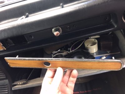
Posted on the parts forum about trying to buy a working kienzle clock. my dash clock and both spares i have when hooked up to 12V do not work. Pretty much got the idea that people sent them out to specialty clock shops paying hundreds of dollars for the work. So i decided what the hell i have the main clock in my dash and two spares in my parts inventory lets open one up and take a crack at doing the repair myself and documenting it for the forum.

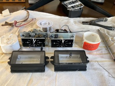
1) having the clock on the work bench you’ll see the plastic white back cover has two nuts and one plastic tamper proof piece. To gain access to the clock movement and gearing this will need to come off.

A2EA0B10-0847-4CFB-8720-51C0DC0F361B.jpeg


2) the tamper proof covers the third 5mm nut that needs to come off. I cut the to small plastic ear tabs on the side of the tamper proof cover with a utility knife then just pride off with a small flat head Screw driver

C5DE2A39-AA14-4126-AEEA-54442EF22F81.jpeg


AF07F32E-FF66-4527-9426-4B4ADE2AD16D.jpeg


3) after sliding off the back cover you can see all the glory of german engineering. upon close examination of the gears, movements and winding mechanism i found a disintegrated soldered joint between the electrical coil and winding mechanism ( I believe it was ground side)

B4A93663-95A9-4AAE-AE5D-58AD337787A3.jpeg


A88AE2BF-3ADB-4925-8813-B3F7F935A779.jpeg


NOTE-on all three of my clocks this soldered joint had failed!!!
NOTE-this picture of the winding mechanism shows the contacts touching when this happens with uninterrupted power the left contact turns clock wise away from the right side stationary contact. This resets the mechanism and keeps the clock turning Until it happens all over again and again and again.

4) I repaired the joint with some 18-20 gauge wire and threaded it between the two eyelets twisted to tighten then resoldered.

0EEF921D-036E-409C-BA6A-94468F3D878F.jpeg


5B214843-B2B5-47CE-8E29-AAD1B8D37625.jpeg


CA8879FB-F52E-448F-88D2-9DF75CE3850A.jpeg


5) I went through the gears lightly blew any grim away and oiled all pivot points. Hooked up the clock to 12v and we were back in business and being on time for it as well. winding mechanism winds, movements move and the sound of the classic tick tick tick are great.

i did this same repair one all three of my VDO clocks and it fixed them all. Saved me a couple hundred bucks and wasn’t that tough to do. Hope this helps others out there.
 
Last edited:

eriknetherlands

Moderator
Site Donor
Messages
2,770
Reaction score
2,006
Location
Netherlands, Eindhoven area
Nice pics and well written process.
@moderator; Perhaps move it to the DIY section?

I think the failed connection is what is elsewhere referred to on this site as a low temperature solder; acting as a kind of heat sensitive fuse: if that is what it is, then it would act if the clock mechanism heats up for some reason, the fuse fails and disconnects the power to the clock, probably keeping the clock from exploding into a pile of very fine gears. .
It's a common failure mode for our clocks; both the old metal can style and your newer white plastic casing version.

I don't think there is a downside to re-soldering it back with normal solder; I haven't read any posts about people doing the repair and then having a cooked clock later on.
 

bmw2800cs

Well-Known Member
Site Donor $
Site Donor $$
Messages
1,147
Reaction score
496
Location
San Jose, California
@vanbavaria how hard is it to remove the clock from the dash? I'm told that you can remove the wood with all of the gauges without removing the windshield but it is a little tricky. Is it possible to remove the clock without the wood and other gauges?
 

vanbavaria

Well-Known Member
Site Donor
Messages
247
Reaction score
133
Location
Vancouver B.C. Canada
Nice pics and well written process.
@moderator; Perhaps move it to the DIY section?

I think the failed connection is what is elsewhere referred to on this site as a low temperature solder; acting as a kind of heat sensitive fuse: if that is what it is, then it would act if the clock mechanism heats up for some reason, the fuse fails and disconnects the power to the clock, probably keeping the clock from exploding into a pile of very fine gears. .
It's a common failure mode for our clocks; both the old metal can style and your newer white plastic casing version.

I don't think there is a downside to re-soldering it back with normal solder; I haven't read any posts about people doing the repair and then having a cooked clock later on.
Yeah I figured it had to be some sort of soldered fusible link, I didn’t realize there was a DIY section on the forum.
 
Last edited:

vanbavaria

Well-Known Member
Site Donor
Messages
247
Reaction score
133
Location
Vancouver B.C. Canada
@vanbavaria how hard is it to remove the clock from the dash? I'm told that you can remove the wood with all of the gauges without removing the windshield but it is a little tricky. Is it possible to remove the clock without the wood and other gauges?
Ill run down to the garage and take some pics to show you the dash. It’s not that difficult.
 

vanbavaria

Well-Known Member
Site Donor
Messages
247
Reaction score
133
Location
Vancouver B.C. Canada
For the E3 clock removal

1) open the glove box and feel up above for the two plastic retainers and unscrew. These hold the wood dash panel in place above the glove box. DO not attempted to remove panel at this point.

AE3BABCA-7E70-4A41-A485-E7DE7299C190.jpeg


2) on the left side of the glove box you’ll see a block plastic elbow air tube. Remove that. This will give you access to the third right side plastic retainer of the wood panel over the ash tray. also remove the little black plastic knobs for the heater controls X4.

5FA10AFE-B13E-405F-A18E-5C6913A98DEB.jpeg


48D81F74-15CE-4014-8F1E-8550125E6B6F.jpeg


3). There is a fourth plastic retainer on the left side of the wood panel over the ash tray accessible under the steering wheel kick panel. It’s a pain to get your hand up in there and i Managed to do the job with out removing this fourth retainer

A9CE8904-0E0F-4832-AAAB-252A4418CF14.jpeg


4) at this point you can very carefully start manipulating the right side wood panel out as well by pushing the left side wood panel out a hair (right side beside clock beauty panel) to give you enough room to also remove the clock beauty cover. NOTE the clock beauty cover tabes that are underneath both wood panels holding it in place!!!!

39BC8B70-059F-42E3-B1A2-752FA984F99B.jpeg
81F4655B-5586-4DD6-8409-FECFA0A44761.jpeg


5) unscrew both smaller white plastic clock retainers behind the dash and your ready to push the clock out forwards into the dash and out in your hands. NOTE its a tight fit when pushing the clock through the dash (at least it was on my bav) so be patient and it will come out.
 

Attachments

  • BCF46D6F-2BAA-4054-8A67-153FFE14F2CB.jpeg
    BCF46D6F-2BAA-4054-8A67-153FFE14F2CB.jpeg
    74.2 KB · Views: 118

zinz

Well-Known Member
Site Donor $$
Messages
1,213
Reaction score
1,216
Location
Austin, Texas
I repaired the joint with some 18-20 gauge wire and threaded it between the two eyelets twisted to tighten then resoldered

Andrew is 100% correct, This is a fuseable link. By hardwiring it you have made it semi-permanent. I'm not sure how many amps that little clock will pull, but I don't think I would wire the connection shut.

I have also repaired many of these electro-mechanical dash clocks over the years. I simply hold the connection shut and re-solder. I don't use any special, low-temp solder and have yet to have one fail again.

Last point is to only use clock oil, and only one drop on the pivot points, as you describe, never on the teeth of the gears. I have found the tiny "q-tips" available at the hobby shops in the scale model section work very well for cleaning these clocks.

These are fabulous mechanisms and there is something uniquely satisfying to hear the Clunk...tick, tick, tick, tick, tick

Ed
 

vanbavaria

Well-Known Member
Site Donor
Messages
247
Reaction score
133
Location
Vancouver B.C. Canada
Andrew is 100% correct, This is a fuseable link. By hardwiring it you have made it semi-permanent. I'm not sure how many amps that little clock will pull, but I don't think I would wire the connection shut.

I have also repaired many of these electro-mechanical dash clocks over the years. I simply hold the connection shut and re-solder. I don't use any special, low-temp solder and have yet to have one fail again.

Last point is to only use clock oil, and only one drop on the pivot points, as you describe, never on the teeth of the gears. I have found the tiny "q-tips" available at the hobby shops in the scale model section work very well for cleaning these clocks.

These are fabulous mechanisms and there is something uniquely satisfying to hear the Clunk...tick, tick, tick, tick, tick

Ed
I agree in hindsight not threading a wire through and instead just strait soldering it is a safer bet. I also used super oil as the pivot point lubricant.
BD8A17C8-2D18-4DA9-9EE9-52B2A8F40FB8.jpg
 

vanbavaria

Well-Known Member
Site Donor
Messages
247
Reaction score
133
Location
Vancouver B.C. Canada
I wish I knew how to post a video of the gears moving the the winding mechanism in action after my repair. It’s pretty cool to watch. Seems I can only post photos.
 

Frederick

Well-Known Member
Site Donor $$
Messages
368
Reaction score
283
Location
Park City,UT
I couldn't decide if the little copper ring went on the inside or outside of the silver hole, or whether it mattered. Looks like original connection was made with a very soft rivet
and not solder. I have two Keienzel, The first one has a wooden looking backing and A black washer between the face and the clock and-a center adjusting knob, the second Has a side adjustment screw on the right and on the left a plus or minus knob which looks like it will adjust the clock if running fast or slow. Can’t really tell which one is older. The one with the left and right adjustment knobs has a sticker on it did 1972 from Hollywood Speedometer and clockworks
 

Frederick

Well-Known Member
Site Donor $$
Messages
368
Reaction score
283
Location
Park City,UT
I sure would like to test them to see if they work I don’t have a 12 V tester.

Looking at them together they’re very different
 

Frederick

Well-Known Member
Site Donor $$
Messages
368
Reaction score
283
Location
Park City,UT
Sorry I was on my PC which has no camera, had to get the iPad
 

Attachments

  • EB054DC9-F2B5-4138-836A-91C363F31530.jpeg
    EB054DC9-F2B5-4138-836A-91C363F31530.jpeg
    379.2 KB · Views: 111

vanbavaria

Well-Known Member
Site Donor
Messages
247
Reaction score
133
Location
Vancouver B.C. Canada
I couldn't decide if the little copper ring went on the inside or outside of the silver hole, or whether it mattered. Looks like original connection was made with a very soft rivet
and not solder. I have two Keienzel, The first one has a wooden looking backing and A black washer between the face and the clock and-a center adjusting knob, the second Has a side adjustment screw on the right and on the left a plus or minus knob which looks like it will adjust the clock if running fast or slow. Can’t really tell which one is older. The one with the left and right adjustment knobs has a sticker on it did 1972 from Hollywood Speedometer and clockworks
The style VDO clocks I was working on are the same as the left one in your picture with the two clock face clock speed (+/-) and clock time adjustment knobs. And for testing I just made two 16 gauge wires with alligator clips hooked up to my bavaria battery.
 

vanbavaria

Well-Known Member
Site Donor
Messages
247
Reaction score
133
Location
Vancouver B.C. Canada
my bavaria is also a 1972.
I couldn't decide if the little copper ring went on the inside or outside of the silver hole, or whether it mattered. Looks like original connection was made with a very soft rivet
and not solder. I have two Keienzel, The first one has a wooden looking backing and A black washer between the face and the clock and-a center adjusting knob, the second Has a side adjustment screw on the right and on the left a plus or minus knob which looks like it will adjust the clock if running fast or slow. Can’t really tell which one is older. The one with the left and right adjustment knobs has a sticker on it did 1972 from Hollywood Speedometer and clockworks
My bavaria is also a 1972
 

Frederick

Well-Known Member
Site Donor $$
Messages
368
Reaction score
283
Location
Park City,UT
RE: testing. I thought about that, but did not want to feed it too much juice. Probably safe.
The clock on the left,(our clock) has an entire movement dedicated to setting the time, the other one did away with that movement entirely.
The knob simply moves the hands! saved BMW some money. But the dual movement clock appears newer, and more sturdy. Silicone seal, heavy plastic backplate.
Plus it has the ability to adjust faster or slower.

Thanks for the inspiration Fun project. Learn something new every day. Just wish I had never seen that heater box thread!
 

Dick Steinkamp

Well-Known Member
Site Donor $
Messages
2,460
Reaction score
2,891
Location
Bellingham, WA
Could the one on the right be a quartz movement? No need to be able to adjust those faster or slower. They keep (near) perfect time. They came after the Keienzel type.
 
Top