
72 3.0 CS 2240344 Restoration

Spent a quiet Sunday afternoon finishing cleaning of the front and rear subframes. Just when you think they are clean, you find another spot with grimy dirt, hiding somewhere..

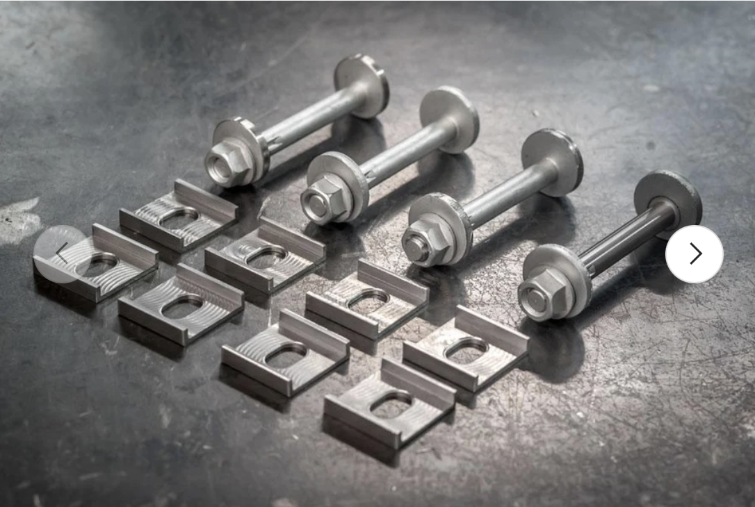
Anyway, once I was sure they were as clean as I can reasonably get them with out a hot-tank, I removed the paint on the trailing arm brackets, fired up my ancient Hobart MIG welder, and welded on a set of Garagistic eccentric brackets. These will allow me to adjust the camber and toe for the rear suspension. With nice clean material the welding went well. I did a few practice pieces, since I have not welded anything in many years.. pretty much like riding a bike! I'll post pics in an update to this thread (had to rush off to a neighbor's happy hour yesterday)...
Screenshot 2026-07-20 at 6.38.04 AM.png

So next up is to take the subframes and struts to be powder coated. While that's being done I'll disassemble the front and rear hubs. I'm doing the rear hubs primarily to replace the decrepit rear brake backing plates...

All of that will go on the shelf while I await the body. Meanwhile I'll start tackling the dash veneer, and my gauge project.
 
Totally off topic. Lotta life going on here in the Andrews clan. My dad passed away at 98 in December, and today I received a video of my first grandson's 6 week old (from conception) heartbeat...Life goes on...
 
Totally off topic. Lotta life going on here in the Andrews clan. My dad passed away at 98 in December, and today I received a video of my first grandson's 6 week old (from conception) heartbeat...Life goes on...
Agree, that does really represent the life spectrum. I think it's part of the appeal of working on an old car, and you're representing that spectrum by using new technologies (3-d printing, e.g.) in pursuit of keeping this half-century old vehicle going.
 
Agree, that does really represent the life spectrum. I think it's part of the appeal of working on an old car, and you're representing that spectrum by using new technologies (3-d printing, e.g.) in pursuit of keeping this half-century old vehicle going.
Gotta have this car ready for "all cars all the time" Bennet (aka Bennie) my wife's youngest grandson.. we gots little boys everywhere (!!), but this one is definitely the car guy!
Screenshot 2026-07-21 at 11.01.11 PM.png
Screenshot 2026-07-21 at 11.06.30 PM.png
 
Same dash, just repaired and re-covered
interesting, I assume it looks good, I wonder how they got it around all the curves? how was installing it? I bought the Just Dashes, I had a hard time with it, with the instrument cover, and the upper part
 
I have not yet installed it.. Still waiting for my car to re-emerge from body and paint
I see, I will tell you, getting the long upper part in was a nightmare, and that part was not a Just Dashes issue
There are little metal tabs that are supposed to snap in to rectangular holes, all sort of issues with that, some fall out, some won't engage, some are too loose
On loose ones, I made hard wood wedges
One the one that would not engage, I bought a small threaded rod, used a welding torch to bend a hook on the end, put a sleeve over it so I wouldn't have to run the nut all the way
 
An
IMG_6354.jpg
d here they are cut out. I ran around the outside edge of the voltage face with a back sharpie to dye the edge black. I'll do the same with oil pressure.
 
That looks great!

I just picked up a gauge, coming from TomHom, this is going to be a future project for me.

Scott, if you can share the files or where to get these printed (no rush) that would be great. Is it your thought that the existing gauge pods will work with new senders or will we need to source the Porsche gauges?
 
That looks great!

I just picked up a gauge, coming from TomHom, this is going to be a future project for me.

Scott, if you can share the files or where to get these printed (no rush) that would be great. Is it your thought that the existing gauge pods will work with new senders or will we need to source the Porsche gauges?
I will be visiting my son in Kennet later in August. I'll drop a set of stickers by. The company (car stickers.com) printed 10 sets...

My plan is to measure the sensitivity of the meters and adjust them accordingly for the senders. The voltage sender is obviously the battery connection (B+), so that one is pretty easy. The oil sender will require some calibration. I thin I can do that will some changes to the internal resistors. VDO oil pressure senders are typically 10 to 180 ohms, so I can mock up a simulated sensor and then work out the appropriate adjustments.

Having seen the Porsche gauge, I think making that work would be WAY more challenging. The most challenging aspect of this one was I had to cut the stickers slightly under sized, because I foolishly used the OUTSIDE measurement of the height of the meter, and there is about 1/2 mm of metal there, so the top and bottom of the sticker had to be trimmed inside the outline by a hair to get the sticker to lie flat. Not really worth re-printing them for that.

Super pleased with how these came out!
 
Last edited:
Clearly these were easy to mount from the back - would you be able to fit them in if dash was still in place? Looks awesome - very well designed!
 
Clearly these were easy to mount from the back - would you be able to fit them in if dash was still in place? Looks awesome - very well designed!
Yes, assuming you can get the old speak out while the dash is in place. You moot the speakers to the plate, and then mount the plate to the dash. I'll drill some holes for the mounting screws and use blind T-nuts to hole the plate in. Then the front plate gets glued to the grille, and attached through the smaller holes, which line up with the slotted holes in the dash.

I made the whole thing slightly thinner, so I can mount some thin felt tape to the back of the plate to prevent rattles. I may use a set of small velcro dots to secure it as well.
 
Been fiddling with the gauges today. Turns out that the gauges have two different characteristics. The fuel level gauge is designed as a traditional meter, where the sender has high resistance when empty, and low resistance when full. So the fuel sender is in series with a fairly conventional meter. Lower resistance means more current flows through the meter and the needle goes up. Unfortunately, the oil pressure sender has the opposite characteristic. High oil pressure, high resistance and vice versa.

So to adapt the fuel meter to do oil pressure, I have to put the sender in parallel with the meter, and then adjust the series and shunt resistances to get the gauge to read properly. The meters all have a small wirewound resistor in parallel, so I suppose that sets the basic sensitivity of the meter, while the series resistor sets the mid point. So I think I can calibrate that. It will definitely require adjusting both of the resistors though.

Converting the temp gauge to a volt meter seems somewhat more involved. I was going nuts measuring the meter because as I increase the current through it, it would suddenly respond to full range, but then as ai lowered the current it would not respond until the current was really low.

I noticed on close inspection that the meters have some small copper component as part of the movement. In the fuel gauge it is not connected, but in the temp gauge it is. Some Internet sleuthing turned up the fact that the temp gauges have a "deadband", where changes in
the sender signal do not result in immediate changes in the meter position. Apparently this is to avoid users freaking out as the temperature of the car varies under normal operation. So, I'll have to re-wire that meter to operate as a conventional galvanometer so I can use it to measure voltage...

So this little project is more difficult than than just making some meter gauge stickers...
 
Last edited:
A tip for placing the tap for the +12V lead for the volt meter....
Take the + tap at a spot that gets consistent power. The positive side of most of the gauges and other things in the dash don't get a clean (and consistent) 12V. For those things, that isn't a problem - but... back in the 1980's, I added an aux volt meter to the 2002 I had and took the + lead from a wire local to where the guage was. The volt meter danced around with my stereo, turn signals, lights. Was a real bouncy reading - anything that pulled power caused a voltage drop where I was and... was kind fun to look at, but not really useful.
S0 - I ran a dedicated line back to the underside of the fuse box instead of a local source. Was VERY stable after that and worked great the following 25 years or so till I sold the car...

For my Coupe - I also had bought a fuel/temp gauge to covert for reading oil pressure/volts as you are doing (and install in place of the clock).
@sfdon had that done for me when he had the car back several years ago.
The problem is that gauge also dances around a fair bit (like my 2002 did). The car is back in his shop currently to have some issues addressed, and this is one of them. I have asked him to take power farther upstream (so to speak) to get a better and more consistent reading. Not sure where he will end up taking power from, but... will see when he gets to that (he is currently going at 100% on getting cars ready for Monterey in a month and will work on mine after)

FYI - There is a gauge set available here if anyone is interested in doing this themselves...

Just my nickel on what I have done (and have to do again).
Good luck
 
Last edited:
Back
Top