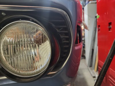
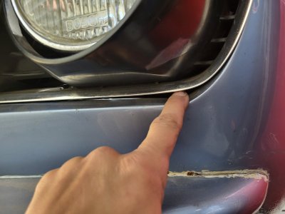
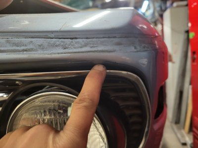
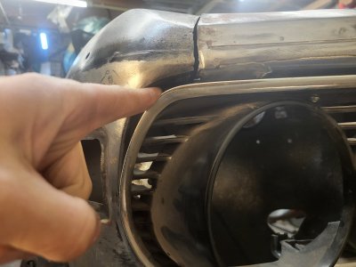
Fixing that little rust spot...

The L-Jet is analog, and pretty simple. There is no ignition control like with Motronic. As you will find reading Probst, basically the concept for L-Jet is to measure the air flow and the air temp (both done in the AFM), and based on that, set the injection duty cycle. The goal here is to meter the fuel to match the number of oxygen molecules. The amount of air depends on the air flow and the air density (temp), and the amount of fuel depends on the duration that the injectors are open. Everything else (idle control valve, throttle position sensor, thermo time sensor, cold start valve, etc.), is all just refinements to handle edge cases.

The L-Jet cars use a Bosch electronic ignition box that gets an engine speed signal from the distributor. I replaced mine with a US made MSD capacitive discharge ignition unit, and big fat MSD plug wires. The MSD has wicked strong spark, and the engine seems to respond well to that. I run (now obsolete) Bosch WR9LS "Silbur" plugs that use a silver electrode.You can usually find them NOS on eBay for about $6 each.

I am not sure if a 123 distributor will fit. If it does, and if it has an engine speed signal output, it might be an interesting upgrade, since the ignition system is otherwise pretty mundane.

For reference, the Motronic system is entirely digital. It uses two crank sensors mounted on the flywheel. One sets the reference for TDC, and the other generates a signal from the flywheel teeth. This essentially creates a clock signal where a single engine cycle (defined by the TDC pulse) is then broken into 58 pulses (actually 60, but they have two missing teeth for some reason). Using that reference, and the same air volume measurement as the L-Jet, they can then adjust the spark as well as the fuel according to a digital engine map (a table of spark advance and injector duty cycles vs engine speed, air flow and air temp). The result is a smoother and more adaptable engine. That said, there is something very visceral and mechanical about the L-Jet M90. Its beauty is that it is NOT refined, it is just strong, like an ox..

I have also found, and @sfdon has confirmed that the M90 does not rev as high as the B35. Fortunately it doesn't need to. Generally the torque comes on at about 1500 RPM, and peaks around 5000, but the variation over that band is fairly small. So you get all that torque early, and it just continues until you shift. It also revs very quickly, probably due to the short rods and short crank throws. The B35 and (especially) the S38 have a rather peaky behavior with peak torque showing up around 3000-3500. As I have written before, the M90 will usually best a B35 or S38 car on twisty roads where the engine rarely gets over 3000 rpm. Above that, and the B35 and S38 will overpower the M90. It also peaks at about 5500 RPM, vs 6000-6500 for the other engines. I am not sure why this is, but with all that low end torque, it is not generally a liability.

I personally like the simplicity of the L-Jet. On my 635, I have to pass the CA emissions test. To do that I have a catalytic converter (which I hope to make removable) and an O2 sensor. Since the ECU has no provision for the O2 sensor input, I developed a circuit that alternately switches in series and shunt resistances to dither the AFM air temp, causing the ECU to dither back and forth around the optimal 14.7:1 Air fuel ratio. SO the system is also fairly adaptable. There are some useful posts on the 528 forum about tuning the AFM as well.
 
Last edited:
The b35 uses Motronic 1.3 and does not use the flywheel from Motronic 1.0, the crank sensor is next to the harmonic balancer on b35.
Good info. I wasn't aware of that.

The point is that the difference between L-Jet and Motronic is that L-Jet is entirely analog, whereas Motronic is digital.

L-Jet basically adjusts the injection pulse duration by comparing a sawtooth wave to a variable threshold. As the air flow increases the threshold moves up causing the resulting pulse from the comparison to grow longer. They do the same with air temperature.


Motronic measures air flow the same way, but they then adjust the timing and injection pulses based on a discrete time base created by the crank sensors (wherever they are mounted). So, the Motronic system basically chops up the engine rotation into small increments, and then controls ignition timing and injector duty cycle based on the sensor measurements compared to a large table (the engine map).
 
...
I have attached a summary of the AFMs and ECUs used on different 6 series cars, so you can locate the right one (these were compiled by an EFI guru on Roadfly (Bill Wolf) back in the early 2000's). I have several AFMs in a box.

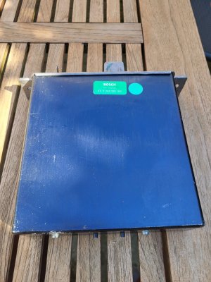
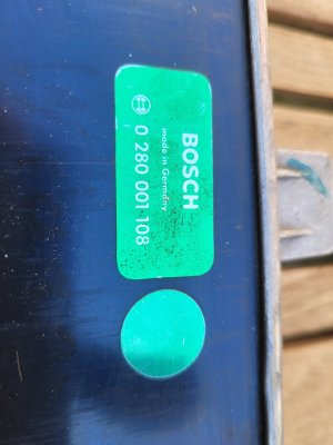
This is the ECU that came with the engine. Type code is 0 280 001 108
Engine is off a 735, and it's number does't come up in your list.
Guess i need another ECU?

If I go into megasquirt/123ignition or K-data system, do those sytems then replace the ECU?
 

Attachments

  • 20260501_105417.jpg
    20260501_105417.jpg
    358.5 KB · Views: 58
  • 20260501_105423.jpg
    20260501_105423.jpg
    209.5 KB · Views: 60
This is the ECU that came with the engine. Type code is 0 280 001 108
Engine is off a 735, and it's number does't come up in your list.
Guess i need another ECU?

If I go into megasquirt/123ignition or K-data system, do those sytems then replace the ECU?
That list was 6 series based. I'd check the VIN on the engine and go to RealOEM to find what ECU was used. The one you have is probably the right one. The number comes up in the L-Jet context.

Others may have different experience, but I'd start with the stock system. Any aftermarket system is going to require a fair amount of dyno tuning to get right.
 
So the basic operation of the L-Jet ECU is shown below. The tach generates a timing signal based on engine speed.

The ECU generates a sawtooth waveform synchronized with this tach signal.

The ECU also generates a threshold signal that depends onthe air flow and the air temp. High air flow, higher threshold. Lower air temp (higher density) higher threshold.

The ECU compares the sawtooth wave to the threshold, and generates an injection pulse. The pulse starts with he task signal, and ends when the sawtooth rises above the threshold.

SO as air flow rises, or air temp falls, the injection pulses get longer (more fuel), and as the air flow drops or the temp rises, the threshold falls, and the pulses get shorter (less fuel).

Simple.. Of course, the devil is in the details!

Scott

Screenshot 2026-05-01 at 2.28.20 PM.png
 
If you already dont have a ECU, maybe its a good idea going directly to a free programmable ECU?
So much possibilities w that....
Breiti
 
Have a look at Haltech Elite 750. I would have gone with the original ecu for my M90 if I'd had it, but am very happy with this. Onboard map sensor, so you dont need AFM, high or low impedence injectors, and much more.
 
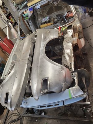
While the engine is away at my engine builder, I'm digging into my bare e9 chassis.

It had a tough life, and some love by the previous owner.

Here's what I can make out looking at the car:

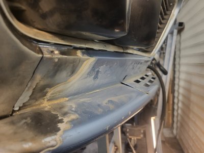
The frontclip is not original to the car, it was replaced at some time as it has the shorter slits in the chin spoiler (post mid '73). Also, it carried a partnumber sticker inside the right front corner behind the headlights. And it has plugwelds where spotwelds should be present.

Both front fenders were split in half and merged again above the front wheel. Quite nicely welded actually!
The fenders were welded back in place, but the 4 angled pieces inside the rain gutter on the engine bay side were never installed back again. Thus there was no rust trap there anymore, but structurally it's quite a sacrifice as the inner fender wasn't connected anymore to the outer fender.
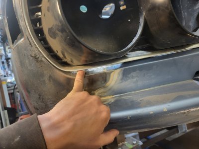
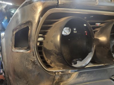
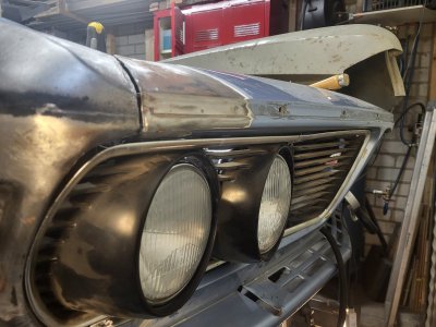
And the grilles of the headlight fitted with thumb size Panel gaps.
20260514_205712.jpg20260514_205721.jpg20260514_205733.jpg20260511_222855.jpg20260511_222904.jpg20260511_222943.jpg
When I reinstall the fenders, I will need to move them.outwards a bit
Curious how the hood will sit when I'm done!

So, with all these scars and stitches, I knew all along that she has been used, and loved before.

The fenders have been off before, and even the structure down to the A-pillars was fixed up before.
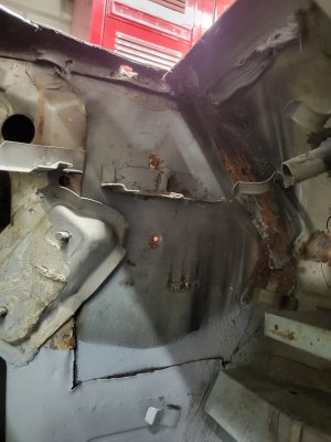
Pandora's box (the notorious grit/water collecting rust trap) recieved a new custom bottom part, and was closed off with new reinforcement plates , the vertical ones that run from A-pillar, halfway to the front. Those reinforcements were welded kinda shabby: On the right side they forgot half of the welds, and on the left side they installed a right hand side part. On the pics you can see the flap inside Pandora's box, where it should be facing outwards.
20260519_213940.jpg

Behind the hood opening latch, inside the glovebox, is a patch to the A-pillar where there must have been a gaping hole.
20260521_103222.jpg

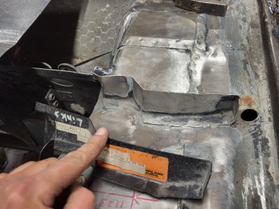
Strangely, also the left extension of the firewall part (that carries the fire wall sealing rubber to the hood) has a funky wobble in it. Luckily I have a NOS bmw part for it.
20260519_210619.jpg
20260519_210632.jpg
Still, I'm thankfull as the PO did save the car from the crusher with all that work. This was never a cheap fix, event hough the rust protection of the fresh welds could have been better: they were just left as bare naked blue steel.

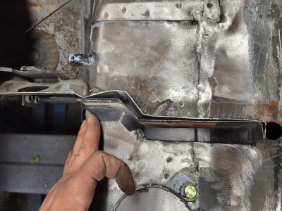
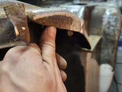
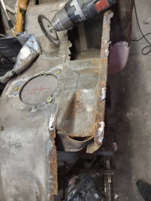
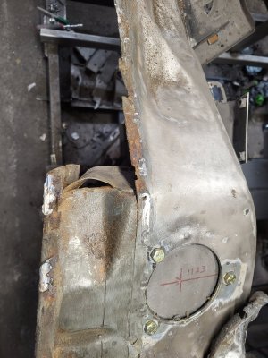
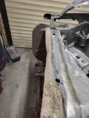
But then on the left side, I noticed today when pulling the fender off, it still caries damage from a crash: the thick reinforcement plate that carries the strut has recieved a whack, as it's side edge is slightly folded in. I'm lucky to have the "copy" of the Celette jig to mount it on, so at least in know the core is straight.
Sideview, where you see the bottom edge has been pushed inwards
20260520_163921.jpg20260520_133713.jpg
Topview:
20260520_133723.jpg

Also the hap hazard welded in feder extension pieces has a dent in it from the left side. Chronologically, it must have had an accident after the nose clip was replaced.
20260519_201220.jpg

Benefit of all the PO's work is that at least I have a full nose clip that is pristine, with just some light rust. Plus 2 fenders that are salvagable, they just need tiny patches here and therenand the W&N lower A-pillar patches to be added.

Still, a long way to go. I'm having a 5 month holiday, so hoping to finish it and get it in a paint shop before work starts again.
 

Attachments

  • 20260520_164329.jpg
    20260520_164329.jpg
    347.1 KB · Views: 19
Last edited:
My speed to get it back on the road is mostly hindered by my desire to reach a high standard. Or at least to push myself and see how far I can take it. (It's a hobby after all).

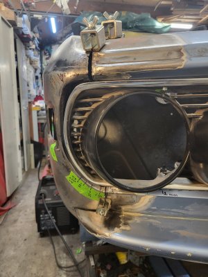
Here's the work on the right head light opening. As per the post above, you've seen the gaps it had where my finger would fit in - not particularly nice.
20260511_223001.jpg
Another thing is that both fender were placed to far inwards by about 2-3 mm, which pushed the grilles forward.
Where normally the grilles fall inside the body, in my car they stood proudly, sticking out by ~2mm. 20260511_222943.jpg

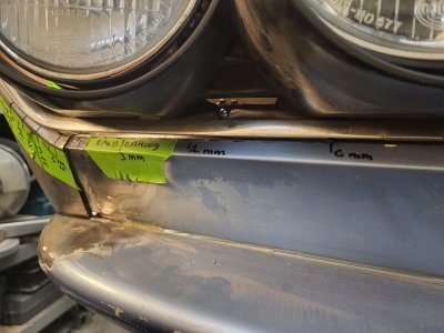
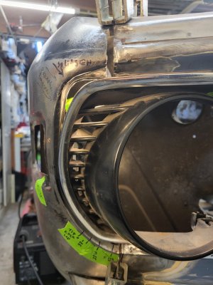
And something that i also see on other cars: the horizontal gaps between the anodized alu trim and the body isn't nicely parallel. In my car it kinks at the top where the middle screw is positioned.20260511_232419.jpg

And at the bottom the gap widens when going further to the corner of the car:
It's close to a zero gap near the kidney, and about 5 mm in the lower outside corner20260511_232428.jpg
So this all needed some reshaping.

I started by trying to understand how it should all look like, originally. Googling pictures showed me many cars that looked alike, and also some that were just as funky. The site from Lezebre has some nice old pictures which tends to show more 'unharmed' cars. Longer life equals more scars, at least for me that's true!

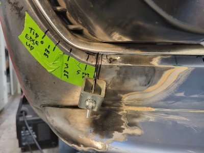
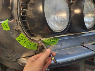
So I figured that the fit of the grille should be like this: fully inside the opening, recessed on it's entire perimeter.
The corner of the headlight near the bottom side of the center grille is set the least deep, about 7 or 8 mm.
That "depth" grows to about 12 mm for the rest of the circumference.

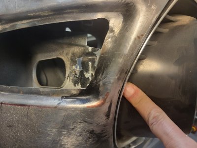
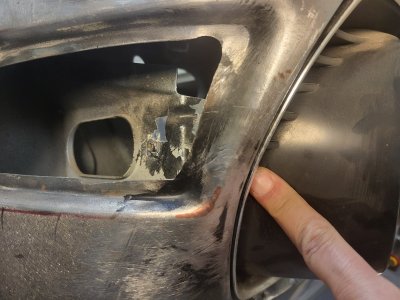
In order to achieve this, I tilted the horizontal lip up and forward, where in the Pic you see the screwdriver poking through. 20260513_140655.jpg20260513_140722.jpg20260513_152900.jpg
20260511_232428.jpg

There I also added a strip of about 2 mm to push the fender out. Here you see how that lower corner starts to look right:20260514_230137.jpg
And how it just makes the top look even more awfull:20260514_230130.jpg

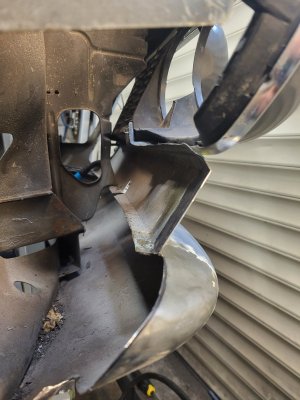
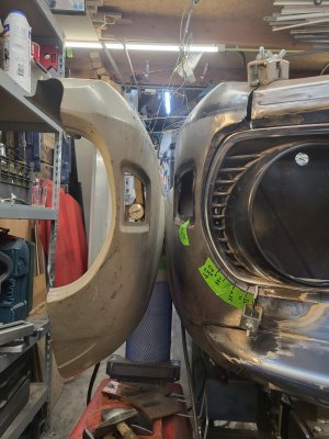
Luckily I have a NOS Panel that I can use to mirror the shape from, so i suspended it next to it, to see the challenge for the top corner. 20260515_153403.jpg
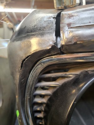
The hole was massive, wrong shape and already thinned by previous grinding actions.
Here's the starting point: 20260514_230204.jpg
And after some cutting and bending, this looked about right. You can also see how a gap opened up where the metal was ground away on the outside sharp corner by the PO.20260515_160105.jpg

Funny side story:
It got an minor dent there when I bought the car, literally 30 seconds after I made the payment at the dealer.
I hugged my wife, proud of realizing the purchase of my dream car for saving up for 10 years when a guy walks in, asks who owns that nice Fjord e9; i proudly say that since 30 seconds it's mine, to which he responds that he backed up into it!
It cracked the blinker glass and pushed the chromed housing into the fender. It was fixed up ofcourse by insurance, but the bondo turned out to be 10 mm (half inch) thick
 
Last edited:
According to Don and Paul, my car has never been in a crash (at least so far as anyone can tell). Would you like me to make a template of the front grille opening?

Also, older question, but my radiator supports are symmetrical.

Car is a 1972 CS
 
I found that area to be one of the trickiest areas on the car… you are making really nice progress. Slow and precise is just what the doctor ordered there.
 
Back
Top