Fuse box upgrade (prototype)

Ezz

Well-Known Member
Site Donor
Messages
170
Reaction score
112
Location
Arizona
Hi,
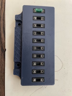
my fuse box contacts had some corrosion and fuses were mostly bad. So i looked at different solutions and came up with PCB mounted fuse holders that fit in the original fuse box.
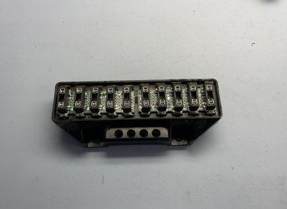
I solder the fuse holders to the PCB and soldered copper strips to each side of the fuse holder then soldered that to the fuse box contacts.
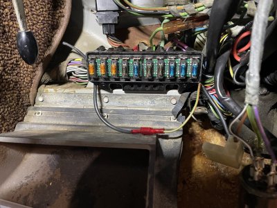
Looks like working well.
Also, working on a more professional looking replacement to the whole fuse box that would have the same quick connect terminals and would be a direct replacement.
 

Attachments

  • IMG_5137.jpeg
    IMG_5137.jpeg
    243.7 KB · Views: 214
  • IMG_5140.jpeg
    IMG_5140.jpeg
    421.7 KB · Views: 217
Last edited:

x_atlas0

Well-Known Member
Messages
1,799
Reaction score
141
Location
Clarkston, MI
Nice! I have seen a couple replacements for other BMWs and Porsches, so this kind of upgrade for our cars would be fantastic.
 

coupesport

Newish Member
Site Donor $
Messages
169
Reaction score
83
Location
Chicagoland, IL
Thanks for your effort. Great idea. Just want say the solder tabs of the fuse holder piece appear to also be the mechanical fastener of the fuse holder. If so... not good. Maybe you already have it on your design list.
I like where you are going with this and will follow. Cudos!
 
  • Like
Reactions: Ezz

Ezz

Well-Known Member
Site Donor
Messages
170
Reaction score
112
Location
Arizona
I appreciate the feedback. They make those fuse holders through hole as well so I will look into using them in the next design while keeping the whole thing compact.
Thanks again
Ezz
 

x_atlas0

Well-Known Member
Messages
1,799
Reaction score
141
Location
Clarkston, MI
Are the E3 and E9 fuseboxes similar enough such that your part would be cross-compatible? Based purely on the part number cross-referencing, the E3 and E1 share a fusebox but not with the E9.

E3:
1694277327116.png


E9:
1694277369465.png


I have a spare E9 fusebox I could send you if you'd be willing to make an upgraded version of it.
 
  • Like
Reactions: Ezz

Ezz

Well-Known Member
Site Donor
Messages
170
Reaction score
112
Location
Arizona
Are the E3 and E9 fuseboxes similar enough such that your part would be cross-compatible? Based purely on the part number cross-referencing, the E3 and E1 share a fusebox but not with the E9.

E3:
View attachment 168076

E9:
View attachment 168077


I have a spare E9 fusebox I could send you if you'd be willing to make an upgraded version of it
That is kind of you to offer. As a start if you send me some pics (front and back) and the schematic if you have one, that might be enough that I can design one.

Are they all 10 fuses?
I can potentially design one that is configurable and can be used on multiple vehicles. Size would be the main limitation but i think there is enough room where the fuse box currently sits….

I would appreciate anyone else posting pics here of their fuse box if different from the above.
 

Ezz

Well-Known Member
Site Donor
Messages
170
Reaction score
112
Location
Arizona
Note that this is a low quality 3D print for fast prototyping
Also, the fuse holders accept the low profile mini fuse (shown above) and the standard size fuse
 

Ezz

Well-Known Member
Site Donor
Messages
170
Reaction score
112
Location
Arizona
Found some info regarding the E9 vs E3.
This is only for the 10 poles/fuses boxes. At some point I will work on the 12 poles fuse box as well (i have schematics). I have looked for the 16 poles fuse box schematic but couldn’t find it on my Bentley manuals.

This is only according to the manuals . If anyone can confirm this info that would be helpful. I do plan on making early E3/E9 and later E9 boxes. 10poles only.
I will also at later time look into the 12 poles boxes.
IMG_5422.jpeg


IMG_5426.jpeg


IMG_5427.jpeg


IMG_5428.jpeg
 

Ezz

Well-Known Member
Site Donor
Messages
170
Reaction score
112
Location
Arizona
Thank you!
Yes, this is helpful as it confirms post 1973 E9s still use the 10 poles fuse box.
 

Ezz

Well-Known Member
Site Donor
Messages
170
Reaction score
112
Location
Arizona
I made some design changes and created two fuse PCBs that will use the same enclosure:
1. Early E3/E9
2. Late E9

I would like to have both PCBs made but I want to confirm the late E9 (post 1973) connections. I think I got it right based on the schematic in the manual, but it would be nice if someone has the late model fuse box can provide a picture of the back where the terminal connections are.


1694653788162.png


1694653564685.png
 

x_atlas0

Well-Known Member
Messages
1,799
Reaction score
141
Location
Clarkston, MI
I'll pull out the harness I have (I think it's from a 73, not sure of the month) and take a pic of the front/back for you when I get back from a business trip.

Any chance you can add a LED per fuse to the PCB? Most of these updated units I have seen include a light to indicate if the fuse is blown or not. It's pretty hard to tell since it's buried close to the firewall under the dash.
 

Bmachine

Well-Known Member
Site Donor $
Site Donor $$
Messages
3,534
Reaction score
1,792
Location
Northern California coast
Here are a few pics of the rear of mine (December '73 build, '74 MY) with the wires attached if that is helpful. As you can imagine, it is very difficult to bring a camera and some lighting back there with all the wires still attached. So Ansel Adams will not feel threatened today. But maybe some of this will help

That seems to match the "E9 from 9/73 on" schematic you posted above

Frame-14-09-2023-04-21-54.jpg Frame-14-09-2023-04-22-37.jpg Frame-14-09-2023-04-23-53.jpg Frame-14-09-2023-04-25-13.jpg Frame-14-09-2023-04-26-43.jpg
 
Last edited:

Ezz

Well-Known Member
Site Donor
Messages
170
Reaction score
112
Location
Arizona
Thank you for the images! That is very helpful
What I am looking for are the connections between fuses. I circled an example shown in one of your images (a connection between #3 and 4):
IMG_5439.jpeg


There should be one between 5&6 right under your finger in the image above and also 9&10
 
Top