Fuse box upgrade (prototype)

Ezz

Well-Known Member
Site Donor
Messages
170
Reaction score
112
Location
Arizona
Hello again, I finally got the chance to work on the fuse box design.
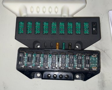
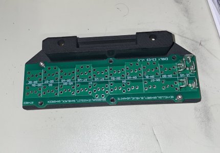
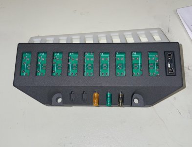
The main update to the design is the additional 4 screws to ensure the PCB is rigidly held to the fuse box body. I also improved the PCB layout but nothing major. The screen shot below missing the spare fuse holders for now. They will be included in the final design.

1701126728047.png
 

Ezz

Well-Known Member
Site Donor
Messages
170
Reaction score
112
Location
Arizona
So far I have made many different iterations for the PCB and enclosure designs... and I was not happy with any of them. Until a few days ago when I took one more stab at it and made this much closer to the origional fuse box dimensions with 3mm longer and wider, but around 5mm shorter. I like this design much better... let me know what you think.

1703531237893.png

1703531145868.png


PCB with burned fuse LED indicators shine through the Fuse itself
1703531278692.png


Early (pre 73) E3/E9 PCB with factory color codings
1703531313226.png


Late (post 73) E9 PCB with factory color codings
1703531333680.png
 

Ezz

Well-Known Member
Site Donor
Messages
170
Reaction score
112
Location
Arizona
The LED indicator is part of the fuse holder/PCB. So yes, it will shine up through the fuse similar to post #25.
 

Drew Gregg

Well-Known Member
Site Donor
Messages
1,574
Reaction score
1,210
Location
Ft. Lauderdale
Excellent design. I had a blown very old fuse that I did not see and I missed a big car show last November. The car stopped dead in my driveway 5 feet out of the garage. Having your design will prevent that from happening again.
 

Ezz

Well-Known Member
Site Donor
Messages
170
Reaction score
112
Location
Arizona
Thank you!
I placed an order for PCBs 10 of each model, but I only have components enough to build two of them. Those two will be to verify the design.
If no further changes required, I will ask again for anyone who’s interested so I can order enough components to build more.
 

Ezz

Well-Known Member
Site Donor
Messages
170
Reaction score
112
Location
Arizona
here is a preliminary list of the parts that will go into this design. I think the 3D print will cost less with higher number of orders.
I am not using any knock-off parts. All components selected are from a reputable vendor. The total below doesn't include the development cost or the labor that will go into building each unit. As of now, I am thinking of $150 per unit. does this sound like a fair price? I am open to feedback. thanks!

1703789255664.png
 
Last edited:

JohnFBD

Well-Known Member
Messages
150
Reaction score
53
Location
Sydney, Australia
here is a preliminary list of the parts that will go into this design. I think the 3D print will cost less with higher number of orders.
I am not using any knock-off parts. All components selected are from a reputable vendor. The total below doesn't include the development cost or the labor that will go into building each unit. As of now, I am thinking of $150 per unit. does this sound like a fair price? I am open to feedback. thanks!

View attachment 174477
Hi Ezz, great work, I just found your thread searching for a better alternative to the stock fuse box as I'm currently rewiring a 74 e9! I think your $150 price point is reasonable. Do you have a timeline on the finished first batch? I would like to put my name down for 1. Cheers John
 

Ezz

Well-Known Member
Site Donor
Messages
170
Reaction score
112
Location
Arizona
Hi Ezz, great work, I just found your thread searching for a better alternative to the stock fuse box as I'm currently rewiring a 74 e9! I think your $150 price point is reasonable. Do you have a timeline on the finished first batch? I would like to put my name down for 1. Cheers John
Hi John,
Thank you!
I started testing the design, but did not complete it.
So far the blown fuse indicator is working as intended. The PCB temperature (trace and terminal connector) is hitting +75 deg C when 30A current is going through it.
The highest fuse rating for these cars is 25A so I over tested it, however, i need to make sure it can handle it.
We will see if I need to re-run the PCBs again after my testing is complete. I will try to share the testing results in details once I am done.
I apologize to everyone for taking so long, but I wi get back to it in the next couple of weeks.

Here are some pics of the current design:
 

Attachments

  • IMG_6537.jpeg
    IMG_6537.jpeg
    356.3 KB · Views: 40
  • IMG_6533.jpeg
    IMG_6533.jpeg
    271.1 KB · Views: 41
  • IMG_6531.jpeg
    IMG_6531.jpeg
    257.5 KB · Views: 39

x_atlas0

Well-Known Member
Messages
1,799
Reaction score
141
Location
Clarkston, MI
Can you use a thicker substrate and increase the solder joint size to distribute your thermal load over more mass? Might help to drop the temps.
 
  • Like
Reactions: Ezz

JohnFBD

Well-Known Member
Messages
150
Reaction score
53
Location
Sydney, Australia
Hi John,
Thank you!
I started testing the design, but did not complete it.
So far the blown fuse indicator is working as intended. The PCB temperature (trace and terminal connector) is hitting +75 deg C when 30A current is going through it.
The highest fuse rating for these cars is 25A so I over tested it, however, i need to make sure it can handle it.
We will see if I need to re-run the PCBs again after my testing is complete. I will try to share the testing results in details once I am done.
I apologize to everyone for taking so long, but I wi get back to it in the next couple of weeks.

Here are some pics of the current design:
Thanks Ezz, I'll keep an eye on your progress, hopefully I can use it on my build ;)
 
  • Like
Reactions: Ezz

Ezz

Well-Known Member
Site Donor
Messages
170
Reaction score
112
Location
Arizona
Can you use a thicker substrate and increase the solder joint size to distribute your thermal load over more mass? Might help to drop the temps.
The current design is 2 layers 1.6mm thick PCB. I am looking into possibly making it 4 layers 2mm thick PCB. Also, I will add thermal vias that are basically through holes that connect all layers to allow better heat transfer.
Another thing is the terminal PCB mount tabs might not be ideal (ratings is 15 Amps).
 

rsporsche

Moderator
Site Donor $$
Messages
10,685
Reaction score
3,714
Location
Atlanta, GA
just wondering outloud. while i am not sure about the e3 wiring (its been a long time since i owned one) ... i am wondering if the wiring is anything like the coupe - with headlights and electric windows running through the fusebox. i know that many e3 have manual windows. if it is similar to the coupe, by feeding power directly to the lights / window motors and using a relay to complete the switch circuit ... perhaps you will reduce the voltage running through the fusebox.
 
  • Like
Reactions: Ezz

Ezz

Well-Known Member
Site Donor
Messages
170
Reaction score
112
Location
Arizona
Thank you for the comment @rsporsche ! I always welcome suggestions for improvement!

There are differences in the wiring between the early E3/E9 and the later E9 fuse boxes. Also, later E3’s got the 12 position fusebox.
While redirecting the high current through a relay is a good idea to protect switches and long run wires from overheating, in my opinion we still want the high current to go through a fuse for the protection.
The idea for this design is to keep it as close as possible to the original design to make it an easy swap with no modification to any of the vehicle’s harness wires or mounting location. By keeping it simple I am reducing the things that can go wrong.

I did some more tests and looks like I need to experiment with different fuse holders and terminals. As well we larger copper areas on the PCB to dissipate the heat. I also looked into @x_atlas0 ‘s suggestion to use heavy copper but using heavier than 2oz gets a little more expensive to prototype. With family and full time job I am moving slowly with this, but making progress overall.

Again, i welcome any suggestions for improvement!

Thank you,
Ezz
 

Bmachine

Well-Known Member
Site Donor $
Site Donor $$
Messages
3,534
Reaction score
1,792
Location
Northern California coast
I am throughly impressed with the dedication and ingenuity you are giving to this project. I am sure this will end up being a very useful item for many. Congratulations!
 
Last edited:
Top