You are using an out of date browser. It may not display this or other websites correctly.
You should upgrade or use an alternative browser.
You should upgrade or use an alternative browser.
Fuse box upgrade (prototype)
- Thread starter Ezz
- Start date
@Ezz
Seeing that you have some competition, I want to support your endeavors and would like to be on the list for one fusebox;
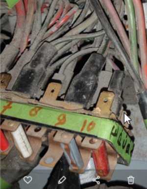
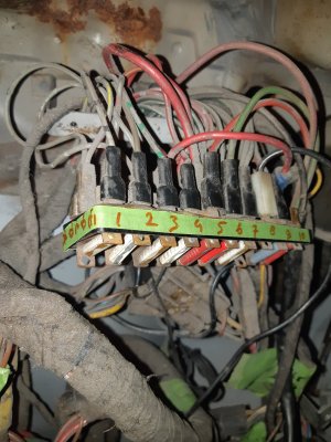
I'm not sure about which version I need, as my car is a May 73 e9 model. I have a 10 fuse version
Does your model also allow the installation of the clear plastic fuse box cover ?
Attachments
Last edited:
Great work!
Definitely interested in a pre ‘73 version!
Definitely interested in a pre ‘73 version!
@eriknetherlands thank you for the support!
You do have the early version fuse box judging by the bussed/connected fuse 9/8 and 7/6

You do have the early version fuse box judging by the bussed/connected fuse 9/8 and 7/6
Currently it does not. The reason is I thought of it as cosmetic and not really provide additional protection since blade fuses are not as flimsy as the original ones. However, i could be wrong. If it is something that should be incorporated, i can look into it.Does your model also allow the installation of the clear plastic fuse box cover ?
Currently it does not. The reason is I thought of it as cosmetic and not really provide additional protection since blade fuses are not as flimsy as the original ones. However, i could be wrong. If it is something that should be incorporated, i can look into it.
It just that I like things to look original.
I would appreciate if it would fit; I'd pay extra for it.
But I know I'm preetttyy ocd-isch in that dept.
Would the fuses not be too high for the cap to fit?
That’s still worth looking into. I will need to source a cover to make measurements and test fit.It just that I like things to look original.
I would appreciate if it would fit; I'd pay extra for it.
But I know I'm preetttyy ocd-isch in that dept.
Would the fuses not be too high for the cap to fit?
Not sure if using the regular size fuses, but definitely will not be a problem with the low profile fuses I was originally intending to use.
I Apologize for taking so long to update. Few changes in life and you know the rest of the story.
However, i am still committed to finish this project with a good solution.
I also acquired a 12 position fuse box for late E3 that I will be looking into.

However, i am still committed to finish this project with a good solution.
I also acquired a 12 position fuse box for late E3 that I will be looking into.
Do you have any estimate as to cost? Your competition in my mind, is not competition since most replacements I bet, will be to bring the car into the 21st century and not because the box is "flaky". Spending that much to upgrade a fuse box that has not caused any issues in 50 years makes no sense to me.
I will try to keep it around $150+shipping. I also posted a list of all major components and part numbers.
It is possible once done, i will make project files free if anyone wants to make it himself. But will see how it goes.
It is possible once done, i will make project files free if anyone wants to make it himself. But will see how it goes.
Hello,
It's been a while since I updated this thread. I have been busy with family and work, but I am trying to get back to this project.
PCB technical issue (heat):
I mentioned a previous post during one of the tests that the PCB temperature was rising to 75 deg Celsius at 25A. I actually did multiple tests after that with different configurations (different fuse holders/fuses) and concluded that the temperature rise is mostly generated at the fuse to fuse holder clip (point of the electrical contact). This make sense that the major heat source is not the PCB because the length of copper run between the fuse holder pins (soldered to PCB) and the PCB terminals is short. However, I still plan to increase the copper weight and think of some other ways to get rid of the heat within reason. A while back I made some improvements to the PCB layout design. I will have to review that and get a quote to order the new PCBs. This run will not include the 12 fuse (later E3 designs) as I have not started this one.
Fuse box housing/enclosure:
there was a request to add the clear cover for aesthetics reasons which I would love to do that, but it will be hard at this time since I lost the access to the SolidWorks license and it might intervene with the ATO style fuse. If someone can send me measurements of the cover, I can look into it. I mainly need the thickness to determine clearance to the fuses.
First run:
Once the PCB is reviewed and ready to go, would there be interest from members here to place a preorder to cover the initial material cost? as a reminder, in a previous post I mentioned a rough estimate of what the material will cost.
If prices did not source that much, I am sticking with $150 per unit.
Thank you,
Ezz
I'll be happy to pre-order
Fuse box housing/enclosure:
there was a request to add the clear cover for aesthetics reasons which I would love to do that, but it will be hard at this time since I lost the access to the SolidWorks license and it might intervene with the ATO style fuse. If someone can send me measurements of the cover, I can look into it. I mainly need the thickness to determine clearance to the fuses.
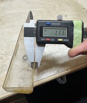
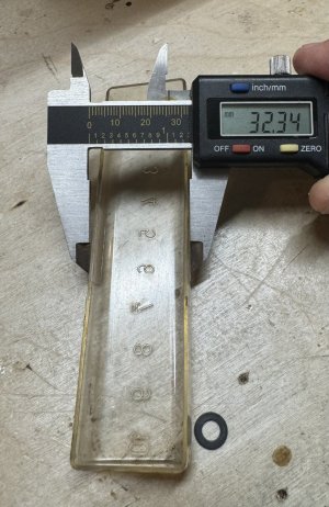
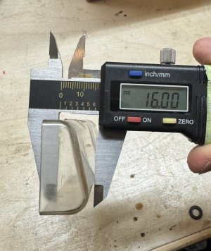
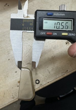
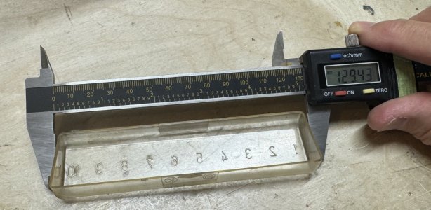
In for pre-order for 1 late model box.
JohnFBD
Well-Known Member
Please count me in for a pre-order
quick update.
I have been working on design improvement for better reliability. I have completed the circuit board layout. I ordered some of the components to test them before I order the first PCB and components batch.
Highlights:
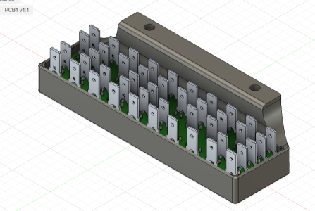
1. Epoxy potting the spade connector side to provide mechanical support. solder alone will not hold the spade connectors, especially with wires, over time due to vibration. solder will crack.
2. spade connectors changed for higher current rating than the previous ones and longer to accommodate for the epoxy layer.
3. changed LEDs to smaller footprint for the proper clearance from the fuse.
4. Redesigned the holder to accommodate the clear cover.
Attachments
jmackro
Well-Known Member
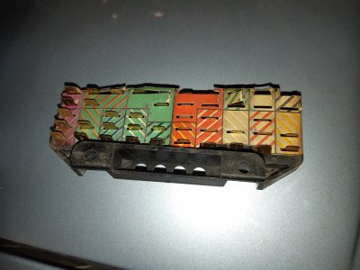
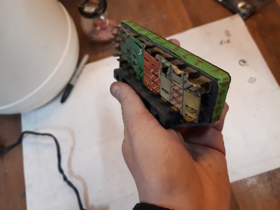
I'm counting 50 spade connectors on the back side of that fusebox and 10 fuse slots on the front. Why 5 connectors per fuse? I understand that some fuses may power 2 or 3 circuits, but are there really 50 wires connected to an e9 fusebox?
The one pictured above is for the early e3/e9 and has 44 spade connectors. The one for the late e9 has less.I'm counting 50 spade connectors on the back side of that fusebox and 10 fuse slots on the front. Why 5 connectors per fuse? I understand that some fuses may power 2 or 3 circuits, but are there really 50 wires connected to an e9 fusebox?
at least in my e3, not all connectors are used.
JohnFBD
Well-Known Member
Looks great, any idea of approximate eta for first batch?

