help, transistorized ignition, original BOSCH

deQuincey

Quousque tandem...?
Site Donor
Messages
8,430
Reaction score
2,443
Location
BIO - 43°15'46.5"N 2°56'03.7"W
hi, i have just bought an original transistorized ignition system from boschconsists of a electronic box and a coil this system is intended to keep the points, but having the benefit of avoiding the major intensity of the current to pass through them, permits a better performanceof the spark allowing a perfect discharge does anyone have information about connections and so on ? i like to know details on the need of specific ballast resistors and how to connect everythingthanks
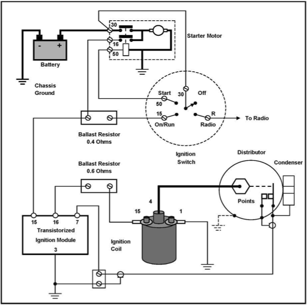
 

jmackro

Well-Known Member
Messages
2,463
Reaction score
728
Location
San Juan Capistrano, Ca.
Only Mercedes Benz could come up with an electronic ignition system as complicated as this. Two ballast resistors? A three terminal starter solenoid? A shielded co-axial cable from the distributor? Sheesh!

JHCrane5.png
 

deQuincey

Quousque tandem...?
Site Donor
Messages
8,430
Reaction score
2,443
Location
BIO - 43°15'46.5"N 2°56'03.7"W
hi i found the instruction of how to connect the transistorized module, it was in the blue manual, yes, do not mention it, i know...


you can see some notes for installation, identifying the cables that i actually have in my car

the question now is the following:

take a look to the distributor (7) that is pictured in the photo above, can you see that they take two signals from it (points A and B) ?

i see no way how to do this with my original distributor of my CS engine

so the question is, are they showing a different distributor type ?

please help
 

deQuincey

Quousque tandem...?
Site Donor
Messages
8,430
Reaction score
2,443
Location
BIO - 43°15'46.5"N 2°56'03.7"W
for comparison purposes here i show the conventional distributor from a CS


you can see here this distributor takes out only one signal (the one from the condensator 1,5 SW 38 )
 
Last edited:

Stevehose

Well-Known Member
Site Donor $$
Messages
13,016
Reaction score
5,693
Location
Sarasota, FL
It looks like the wire from the coil to the points goes to the transistor unit, then the transitor unit goes to the distributor. The unknown distributor looks to not have points, rather some sort of electronic type. Or could it be a csi distributor, do they have additonal wires? Sorry I don't have any experience here.
 

Arde

Well-Known Member
Site Donor $
Site Donor $$
Messages
4,732
Reaction score
1,948
Location
Cupertino, CA
Looks like the cable between the distributor and transistor module is a coax cable or other shielded cable. Point B is the shield at the distributor and can be probably a ground taken really close to where point A mates.

If I knew what the G symbol is I could tell if this is a special distributor.

There is no harm in connecting it to just point A, worst case you will have no spark but if it misfires and you get a flame out of the exhaust, or exhaust into the intake, or blow up your exhaust my lawyer says no harm because I am not liable for advise you did not pay for. But I did not pay him either.
 

Tierfreund

Well-Known Member
Messages
545
Reaction score
1
Location
Duesseldorf, Germany
Our DQ: always has to make it hard for himself. Instead of just puttin a pertronix in ther in be done in 5 minutes he has to get period correct for his upgrades...
Brother DQ: big respect to you, I applaud you!
:)
 

deQuincey

Quousque tandem...?
Site Donor
Messages
8,430
Reaction score
2,443
Location
BIO - 43°15'46.5"N 2°56'03.7"W
It looks like the wire from the coil to the points goes to the transistor unit, then the transitor unit goes to the distributor. The unknown distributor looks to not have points, rather some sort of electronic type. Or could it be a csi distributor, do they have additonal wires? Sorry I don't have any experience here.

yes steve, it seems to be a non-points distributor, in other drawings for this setup the distributor is shown representing a sort of solenoid between A and B, this can be the case of the distributor for the CSI cars

i am not considering to buy a csi distributor it makes no sense, lets see if there is another way,...
thanks
 
Last edited:

deQuincey

Quousque tandem...?
Site Donor
Messages
8,430
Reaction score
2,443
Location
BIO - 43°15'46.5"N 2°56'03.7"W
Looks like the cable between the distributor and transistor module is a coax cable or other shielded cable. Point B is the shield at the distributor and can be probably a ground taken really close to where point A mates.

If I knew what the G symbol is I could tell if this is a special distributor.

There is no harm in connecting it to just point A, worst case you will have no spark but if it misfires and you get a flame out of the exhaust, or exhaust into the intake, or blow up your exhaust my lawyer says no harm because I am not liable for advise you did not pay for. But I did not pay him either.

apart from your endless irony mode on (keep it going on :grin:), you are right on the coaxial cable, the diagrams comming from the mercedes link that jerry kindly offered us before show the same type of cable, a coaxial with shield connected to ground

i tend to think that this is probably the good way to proceed, remove the condenser, take the signal comming from the points and bring it to number 7 use a shielded cable connect the shield to the distributor body (ground), and then to number 31d

you can see that 31 is ground too, so 31d might be d-istributor ground,...makes sense ?
 

deQuincey

Quousque tandem...?
Site Donor
Messages
8,430
Reaction score
2,443
Location
BIO - 43°15'46.5"N 2°56'03.7"W
Our DQ: always has to make it hard for himself. Instead of just puttin a pertronix in ther in be done in 5 minutes he has to get period correct for his upgrades...
Brother DQ: big respect to you, I applaud you!
:)

ha, ha, ha, my "brother in bayerische", thank you,

...i am tempted by 123steve, but lets see what i can get from this one,...i love the idea that is behind this system, and, i must confess, i love the "periodcorrectness", it is SO BLUE !
 

Stevehose

Well-Known Member
Site Donor $$
Messages
13,016
Reaction score
5,693
Location
Sarasota, FL
I totally understand this. But if you don't like the transistor system and before the 123Steve, you should try a pertronix and leave the capacitor on the distributor (disconnected) for the visual. Since your engine is totally stock, this may be all you need.


i love the "periodcorrectness"
 

Arde

Well-Known Member
Site Donor $
Site Donor $$
Messages
4,732
Reaction score
1,948
Location
Cupertino, CA
apart from your endless irony mode on (keep it going on :grin:), you are right on the coaxial cable, the diagrams comming from the mercedes link that jerry kindly offered us before show the same type of cable, a coaxial with shield connected to ground

i tend to think that this is probably the good way to proceed, remove the condenser, take the signal comming from the points and bring it to number 7 use a shielded cable connect the shield to the distributor body (ground), and then to number 31d

you can see that 31 is ground too, so 31d might be d-istributor ground,...makes sense ?

I think connecting just a wire to pin 7 will work. Even if left unshielded and getting some AC noise the bipolar transistor shown mostly responds to input current not voltage, so the coupling will be minor (how much coupled current can one get?). It may reduce the spark a bit if the coupling happens during the discharge phase, or increase the spark if it happens way before.

The logic of installing this circuit epitomizes why our E9 mindset is borderline irrational. Replace the $5 distributor points, 5 grams of weight, almost zero resistance, with a semiconductor that will waste half of the power, weighs 1kg, and when it stops working it will take you a week to troubleshoot and three months to find another unit, all of that for no extra power in the engine. Flawless logic.

Just like a lawyer I know that said during his top firm interview that he can articulate in 100 words what can be said in 10 words, and was hired.

Endless Irony, the title of my next book... Thanks DQ.
 
Top