e9L , any luck?

You are using an out of date browser. It may not display this or other websites correctly.
You should upgrade or use an alternative browser.
You should upgrade or use an alternative browser.
Some help getting engine started
- Thread starter e9Leveque
- Start date

I love that you’re as invested as I am in this. Not yet but mainly still due to lack of time. I have time tomorrow afternoon but then am gone for weekend. So shooting for tomorrow. I’ve been spending some of the evening time when I just have 30 minutes finishing up some of the wiring in the interior.e9L , any luck?
Ok I’m worried I have my starter wired incorrectly and that perhaps this is part of the problem.
1. Starter has been changed to an SR444x as others here have suggested
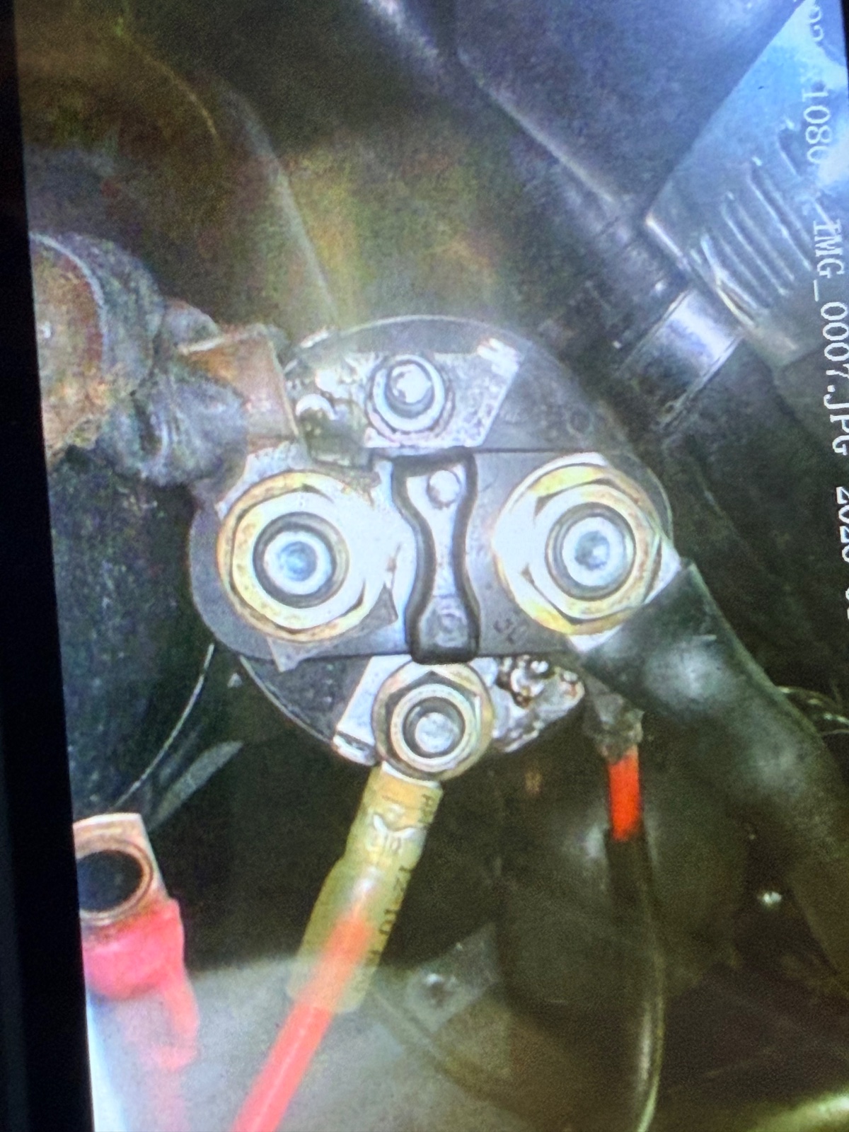
2. If I run a jumper from battery positive to the 6:00 position the starter fires. That is the red wire in the 6:00 position in the photo. The wire from the ignition is temporarily disconnected since I had the jumper hooked up
3. I have battery cable running to the large terminal (large black wire in picture)
4. There is a plastic-sheathed set of two wires with the white one (with red heat shrink at its end) hooked up also to the same terminal as the battery cable. The other end of this white wire is hooked up to the positive of the ignition coil. The Pertronix red cable is also hooked up to this ignition coil positive while the pertronic black and green tach wires are hooked up to negative. No ballast since it’s a Bosch blue coil
The part that seems odd to me Is the cable to ignition coil also hooked up to the same large post as the battery cable - did I do this wrong? When I changed over the starter I tried to follow the instructions for how to move the wires from old style starter to this…
1. Starter has been changed to an SR444x as others here have suggested
2. If I run a jumper from battery positive to the 6:00 position the starter fires. That is the red wire in the 6:00 position in the photo. The wire from the ignition is temporarily disconnected since I had the jumper hooked up
3. I have battery cable running to the large terminal (large black wire in picture)
4. There is a plastic-sheathed set of two wires with the white one (with red heat shrink at its end) hooked up also to the same terminal as the battery cable. The other end of this white wire is hooked up to the positive of the ignition coil. The Pertronix red cable is also hooked up to this ignition coil positive while the pertronic black and green tach wires are hooked up to negative. No ballast since it’s a Bosch blue coil
The part that seems odd to me Is the cable to ignition coil also hooked up to the same large post as the battery cable - did I do this wrong? When I changed over the starter I tried to follow the instructions for how to move the wires from old style starter to this…

my wiring is different since i'm using megasquirt ... Don's harness does things a little differently. the standard e9 wiring has the big black wire going to the big lug on the solenoid on the right (3:00 - where you have it attached) ... that is the big feed from the battery.
other than the big black wire, there is a black / red wire that goes to the coil (that has been deleted on my harness as megasquirt does it a different way). i cannot advise you on this connection.
the other wires that connect at 6:00 would be the pair of black 14 ga wires - one goes to the ignition switch and the other goes to the program tester.
there is a 10 ga red wire that either connects the battery to the alternator OR goes from the starter to the alternator. if it runs from the starter, that would be from 3:00
so the basic operation is to feed the starter with power and when the ignition switch is turned, it engages the solenoid to push the starter on. if the engine will turn when you turn the key, the basics are done ... you just have to sort out the power to feed the coil. my guess is that would come at 12:00 on your solenoid, but since i don't have that wire, somebody else is going to have to help you. i also see a lot of red wires in the picture ... confusing as most of the wires should be black.
other than the big black wire, there is a black / red wire that goes to the coil (that has been deleted on my harness as megasquirt does it a different way). i cannot advise you on this connection.
the other wires that connect at 6:00 would be the pair of black 14 ga wires - one goes to the ignition switch and the other goes to the program tester.
there is a 10 ga red wire that either connects the battery to the alternator OR goes from the starter to the alternator. if it runs from the starter, that would be from 3:00
so the basic operation is to feed the starter with power and when the ignition switch is turned, it engages the solenoid to push the starter on. if the engine will turn when you turn the key, the basics are done ... you just have to sort out the power to feed the coil. my guess is that would come at 12:00 on your solenoid, but since i don't have that wire, somebody else is going to have to help you. i also see a lot of red wires in the picture ... confusing as most of the wires should be black.
(my post here was likely more confusing than helpful / don is right below - I’ll study the schematic and then report my success )
Last edited:

We need to talk and you need to study the Djet schematic. The two thick gauge black wires from the ignition switch go into that plastic casing out of the plastic casing comes a red wire and two white wires. The first white wire starts the cold start injector relay the second white wire tells the computer you’re cranking the engine the red wire goes to the 6 o’clock position or the Crank position on your starter.
There is another thick gauge red wire, and it goes to the power terminal on the starter, and it originates at the main relay.
Eight hour difference between Portugal and Seattle, call early. I have dinner plans at 7 PM my time- there’s a new Mexican restaurant in town!
There is another thick gauge red wire, and it goes to the power terminal on the starter, and it originates at the main relay.
Eight hour difference between Portugal and Seattle, call early. I have dinner plans at 7 PM my time- there’s a new Mexican restaurant in town!
Thanks Don, your help is always appreciated. And I will study the schematic. It’s like I’m back in school - study up and then ask focused questions.
The schematic is a known errata for missing color of red and what other wiring harness could there be that all the other wires are one color white with tiny little numbers on them….
Two red wires go to the starter one from the main relay and one from the ignition switch plastic connector where two black wires go in and one red wire and two white wires come out.
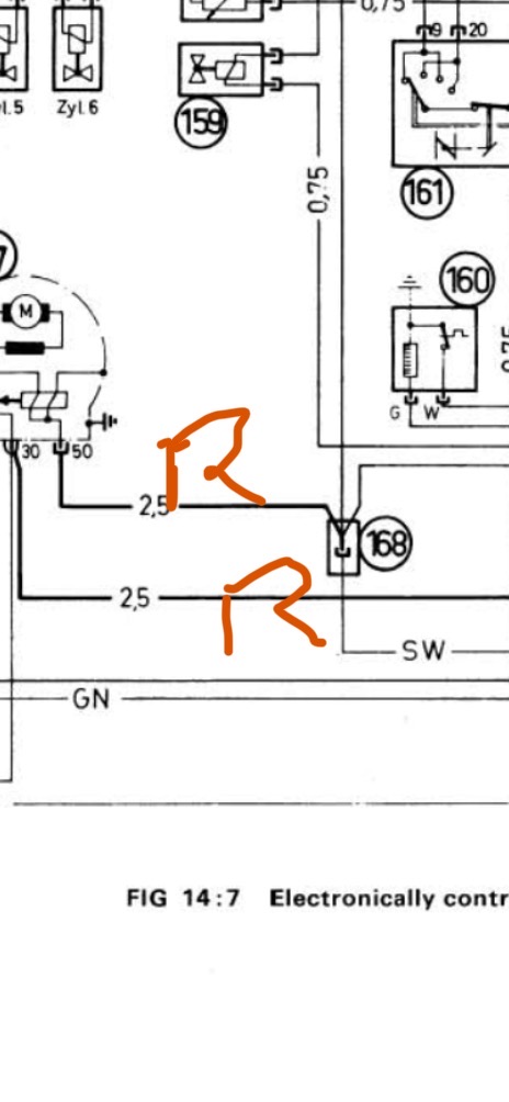
The red wire with the 8mm lug connector at starter goes to the main relay. To be sure you can pin out the center wire of the main relay for conductivity to the large lug connector red wire.
The red wire with a female spade at the starter is the crank signal.
In your case, you changed the starter and so you will use a smaller lug 6mm for crank signal.
And finally- you should have a big black cable going from your battery positive terminal to the starter where the red wire with a 8 mm lug is.
Number 168 in the schematic is that plastic sleeve that you see. Two black wires go in and two white wires and a red wire come out.
The schematic only shows one black wire, but there are two one to the ignition switch to crank and one to the diagnostic plug.
Sounds crazy - black wires connected to red wires and black wires connected to red wires and white wires, but that’s how they did it back then.
Have fun!!
The red wire with the 8mm lug connector at starter goes to the main relay. To be sure you can pin out the center wire of the main relay for conductivity to the large lug connector red wire.
The red wire with a female spade at the starter is the crank signal.
In your case, you changed the starter and so you will use a smaller lug 6mm for crank signal.
And finally- you should have a big black cable going from your battery positive terminal to the starter where the red wire with a 8 mm lug is.
Number 168 in the schematic is that plastic sleeve that you see. Two black wires go in and two white wires and a red wire come out.
The schematic only shows one black wire, but there are two one to the ignition switch to crank and one to the diagnostic plug.
Sounds crazy - black wires connected to red wires and black wires connected to red wires and white wires, but that’s how they did it back then.
Have fun!!

I’ve never seen a coil wire hooked up to the starter solenoid! It would be hot all of the time. Coil wire runs across rad panel.
Yes. I would think so. Main problem is that I’m not getting a spark from the ignition coil output wire. I’m out of town this weekend but when back am going to sit down with the schematic and actually trace out what is connected where. Part of the issue is that I would love to find a color version of the CSi wiring diagram but can’t seem to locate one here on the site. I have the blue books so will sit down with their German abbreviations and decipher…
its in the wiring diagram ... black + red leaves starter (16 post) and goes to the 16 post on the coil - see below. its in the main harness that runs around the front of the car (past the headlights). i know its there as i removed mine since Don feeds the coil in a different direction with the megasquirt harness.I’ve never seen a coil wire hooked up to the starter solenoid! It would be hot all of the time. Coil wire runs across rad panel.
Scott, That is the ballast bypass wire which is hot only when solenoid is engaged. It isn’t used in the new starters.
i know i'm not using it, the question was - is it still on JC's car?
that black / red wire connects to the coil and then leads to the primary resistor #27, then onto 115 (revolution switch - only on USA models) i keep forgetting that JC has a CSi ... it still goes to coil 16 but doesn't show much afterwards - cold start.
that black / red wire connects to the coil and then leads to the primary resistor #27, then onto 115 (revolution switch - only on USA models) i keep forgetting that JC has a CSi ... it still goes to coil 16 but doesn't show much afterwards - cold start.
I did remove the ballast from the system at the moment since I’m using blue coil under Don’s direction since the ballast was getting red hot. I am thinking my problem is that I do not have any wire connected to the 16 terminal on the starter. I have the ignition input wire (or currently jumper) connected to thr 50, the battery to the B+, but nothing on the other terminal. I do remember that when I installed this starter I found a thread stating that when moving to the new style starters the hookup to the B+ was different and I may have misunderstood that. When I’m back at the car I’ll assess.
And Chris, isn’t the black/red wire that should be removed between ignition coil positive (16) and ballast, rather than from starter 16 black/red to starter?
I think main thing for me to figure out is what wire I currently have connected up to the B+ along with the battery cable and then using the schematic place it in the right location. Let me do that and then I’ll get Don on the line and he will put ne straight!
And Chris, isn’t the black/red wire that should be removed between ignition coil positive (16) and ballast, rather than from starter 16 black/red to starter?
I think main thing for me to figure out is what wire I currently have connected up to the B+ along with the battery cable and then using the schematic place it in the right location. Let me do that and then I’ll get Don on the line and he will put ne straight!
OK, forget terminal numbers. The 12:00 terminal (16 it appears) on new starters is not used since it hot 100% of the time, that would turn ballast cherry red. Green wire from ignition switch goes to ballast, you removed this which is fine for a blue coil, with a ballast a black/red then went to coil positive. You should now have the green wire go direct to coil positive since no ballast. Pertronix always needs 12v, if you still had a ballast which you don't the red wire to the Pertronix would come from before the ballast, now it can come from the positive terminal on coil.
Thanks Chris. I’ll assess. I realize part of my problem is that if I was just reinstalling my old starter I wouldn’t have these issues since I could just follow the wiring. New starter, different wiring, etc I think is where I have gotten a bit lost. Your instructions are clear. I’ll check wires and colors when at home and reconnect.
Great. New starter just means one less wire from 12:00, remove completely from both ends as Don will tell you what can happen.

In the diagram posted by @rsporsche, the black and red wire gets energized by the starter solenoid. It goes directly to the coil thereby bypassing the ballast resistor. When the car is cranking this provides a higher voltage to the coil than what would be obtained by energizing the coil through the ballast resistor (27 in the diagram above). So the ballast resistor bypass does not need to actually go to the ballast resistor, it essentially goes around it from a circuit perspective.
then ballast resistor, you should see 12 volts on post 16 of the coil when the ignition switch is on.
In the diagram above you can see that the other end of the coil primary is post 1. That goes to the distributor points (or in your case one end of the Pertronix unit). I am not totally sure where wire 33 goes (it is also connected to post 1), but it appears that it goes to the test connector 37, and then off somewhere else. If I had to guess, that would be to the tachometer.
I am curious that you say the ballast resistor was getting red hot. There is no reason that should happen unless the coil primary is shorted to ground. Normally the coil primary has enough resistance that it drops 12 volts when the ignition is on and the points are closed (with ballast resistor this would be reduced somewhat by the ballast resistor, so maybe 9-10 volts).
As a test, you might disconnect the wires from the #1 post on the coil, and measure the resistance to ground. This should vary from around zero to very high (10K-1M ohm) depending on whether the points are open or closed. Rotate the engine by about 60 degrees and you should wee this resistance change between zero and some high value. If the resistance is stuck at zero ohms (or near zero) then either something downstream is shorted, or the Pertronix unit is shorted. You can sort this out by separating the Pertronix wire from wire 33. If 33 is shorted, then something is shorted downstream. If these check out, then measure the resistance between terminal 1 on the coil and ground. That should have very high resistance. You can also disconnect the wires from post 16 and measure the resistance between post 16 and ground.If pin 1 is not connected, then the resistance between 16 and ground should be infinite. If it is shorted, then the coil is bad (which would explain the red hot ballast resistor...).
Per my tutorial above on Kettering ignition, in normal operation (not cranking, but with the ignition on) the hot side of the coil should be about 10-12 volts, and the other side should be either zero or 10-12 volts, depending on the rotation angle of the engine/distributor. The coil doesn't care where that voltage comes from as long as it stays on while the engine its running.
then ballast resistor, you should see 12 volts on post 16 of the coil when the ignition switch is on.
In the diagram above you can see that the other end of the coil primary is post 1. That goes to the distributor points (or in your case one end of the Pertronix unit). I am not totally sure where wire 33 goes (it is also connected to post 1), but it appears that it goes to the test connector 37, and then off somewhere else. If I had to guess, that would be to the tachometer.
I am curious that you say the ballast resistor was getting red hot. There is no reason that should happen unless the coil primary is shorted to ground. Normally the coil primary has enough resistance that it drops 12 volts when the ignition is on and the points are closed (with ballast resistor this would be reduced somewhat by the ballast resistor, so maybe 9-10 volts).
As a test, you might disconnect the wires from the #1 post on the coil, and measure the resistance to ground. This should vary from around zero to very high (10K-1M ohm) depending on whether the points are open or closed. Rotate the engine by about 60 degrees and you should wee this resistance change between zero and some high value. If the resistance is stuck at zero ohms (or near zero) then either something downstream is shorted, or the Pertronix unit is shorted. You can sort this out by separating the Pertronix wire from wire 33. If 33 is shorted, then something is shorted downstream. If these check out, then measure the resistance between terminal 1 on the coil and ground. That should have very high resistance. You can also disconnect the wires from post 16 and measure the resistance between post 16 and ground.If pin 1 is not connected, then the resistance between 16 and ground should be infinite. If it is shorted, then the coil is bad (which would explain the red hot ballast resistor...).
Per my tutorial above on Kettering ignition, in normal operation (not cranking, but with the ignition on) the hot side of the coil should be about 10-12 volts, and the other side should be either zero or 10-12 volts, depending on the rotation angle of the engine/distributor. The coil doesn't care where that voltage comes from as long as it stays on while the engine its running.
Scott, i was wondering the same thing until Chris mentioned that in new starters, the 12:00 pole is hot all the time. we know the 3:00 is hot all the time - where the battery connects and the 6:00 is triggered by the ignition switch.
so this is something that i learned today ... i had no idea that the other side of the solenoid was hot all the time.
so this is something that i learned today ... i had no idea that the other side of the solenoid was hot all the time.