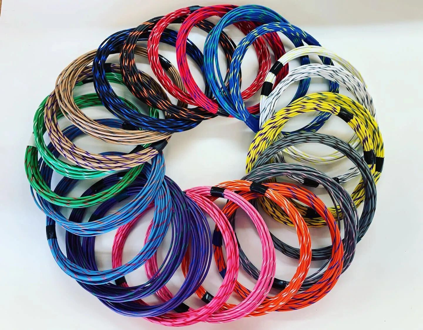
Wiring harness strategies.

I think a good place to start woudl be to catalog the wire colors. There are a lot of them. If making a new harness, I think using the original colors woudl be essential.
 
Florida for wire…


most shops keep 10-20 old harnesses in bins to be able to match wire colors and gauges.

I probably have a mile or two of old harnesses
 
Last edited:
Years ago was hunting down an issue and noticed the injection harness (3.0Si maybe?) was white numbered wires. Tiny numbers but as I am partially color blind having wires numbered to match the numbers shown on wiring diagrams seemed like a great idea. Cheap labelmaker has been a faithful companion. There is also electricians numbered tape in rolls. Wrapping/clear taping a length of original color wire near the ends of replacement wire is also common marker.
1727656302712.png
 
Which software do you use to do that?
Would be great when you share your work with us.

Breiti
 
are you using autocad or one of the autocad family of CAD programs that are compatible with autocad? i draw in autocad, and if i can help you do this, i would be happy to help.
 
I'm going to restore my harness. I'm digitizing the electrical diagram and I'm going to divide it into 10 diagrams 1 for each fuse to make it easier to check.
That's handy for troubleshooting.
For making a new harness, I think I am going to make a wire list using the original numbering and color coding for the wires.

Then I am going to draw the harness in terms of which wires are bundled with which other wires, so then you have a non-scale drawing of the actual harness, with all of the connectors and splices, etc.

The issue really is that the wiring diagrams are "electrical", illustrating which wires connect to what components. Unfortunately, the car is geographic, so some wires with unrelated functions but going to similar places in the car, are bundeled together. Examples are all the front headlamp, turn signal, parking lamp wiring, the washer pump wires, the horn, and probably the coil wiring, which all run together from the fuse box across the front of the car, with bits splitting off to each corner. So making a physical layout is essential.

I replaced the harness in my 72 Bronco using a Painless unit. That worked well. I found that using split braids and zip ties worked well to bundle the wires, but that isn't really very period correct, so wrapping with hockey tape or something similar is probably more appropriate.

To make a new harness, you actually lay it out on a big board with nails or pegs to attach the wire runs. Then you either start wrapping with friction tape, or you use a braid to hold the bundles.

The other way to do it is to simply replace every wire, one after another, and then wrap it in situ.

SFDon's link to Florida Wire looks great!!!

Scott
 
Last edited:
Found a nice clear wiring diagram in my blue-book manual. Scanned it and am currently touching up the diagram to fill in the faded parts. Will post that and a full wire table soon. NOTE. this is for the US CS models. The EU models may be different, and the CSi models will have additional wiring for the injection system.
 

Attachments

  • E9 Wire Harness.pdf
    7.1 MB · Views: 2,789
look at the FAQ - https://e9coupe.com/forum/threads/e9-parts-dimensions-drawings-technical-info-and-models.43743/
in post #7 there are several complete wiring diagrams from the blue book
What I did was to go through the diagram for the 3.0 CS USA model and catalog the wires by number, size and endpoints. Next step will be to sort these into geographic bundles. This may be somewhat iterative, and I'd appreciate other's experience and insight as we develop an actual harness diagram from the overall wiring diagram.

Already in developing this table I found that many wires in the diagram are local, for examples jumpers between two nearby components, and others are physically isolated from the main harnesses (examples being the power window harness, and the instrument cluster).

In my fairly careful examination of the wiring diagram I was unable to locate a few wires. Not sure if they are really not used or I just missed them, despite pretty extensive searching. These are: 2, 163, and 164.

I think a lot of this will come down to two or three harnesses. There is the harness up front that runs across from the left side to the right. I think that ends at the fuse box and at connectors I and II. THen from there the mates to those connectors lead tot he interior and trunk/tail lamp wiring. For cars with power windows, there will be a second harness that leads fromthe center consoleand switches out to the windows. You cna see that that connects tothe main nterior harness at wires 239 and 240.

These two harnesses will have a variety of smaller connectors and terminals as the wires branch off. Would be cool to get a sleeve marker so we could put numbered sleeves on each wire to identify it.

https://www.bradyid.com/wire-cable-labels/heat-shrink-sleeves

Anyway, here is the wire list (attached)...
 

Attachments

  • E9 Wire Harness Table.xlsx
    24.3 KB · Views: 50
Last edited:
I'm going to restore my harness. I'm digitizing the electrical diagram and I'm going to divide it into 10 diagrams 1 for each fuse to make it easier to check.
That's a great diagram!! Exactly what I was thinking of doing. The diagram gets much clearer when you remove all of the complex subassemblies and only look at connectors and terminals.

Now all we need is some way to impose dimensions, and identify wire bundles.

BTW, I noticed in the E9 diagram, there is really only one "splice"(in the headlamp circuit), but there are a number of small connectors that seem to join multiple wires. In the later ETM for the 635, BMW went to a slightly different convention separating splices and connectors, and providing detailed locations for each of them.
 
does it have translation (save as) to autocad or dxf formats?
Yes, ArchiCAD can translate to different platforms. I typically save as a DWG file for my consultants who use AutoCAD. I did my custom wiring harness in ArchiCAD. Saving and then viewing as a PDF file then allows you to zoom in to see the wiring detail much better.
 
Back
Top