
You are using an out of date browser. It may not display this or other websites correctly.
You should upgrade or use an alternative browser.
You should upgrade or use an alternative browser.
3D Printed elements of air conditioning/ventilation systems.
- Thread starter Lucas
- Start date

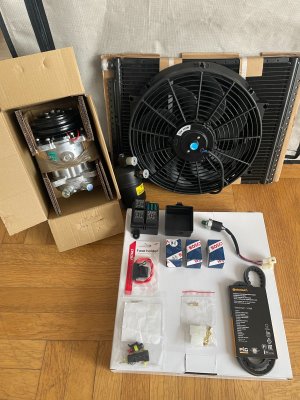
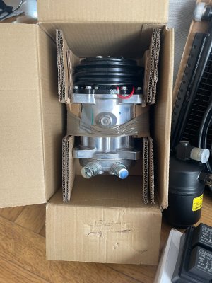
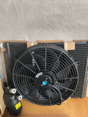
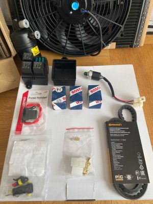

Do you have a bracket for the compressor?
Yes, we have designed a new mount for our compressor from scratch, and it will be CNC and laser-cut next weekDo you have a bracket for the compressor?
Tomorrow marks the official launch of the new, updated full air conditioning system, complete with a detailed description; to mark the occasion, we are hosting an exciting contest with attractive prizes.
Last edited:

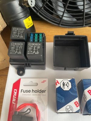
Question: why three relays?
why three relays?
Safety considerations and proper installation requirements for three high-power devices:
7-piston compressor.
Condenser fan.
Evaporator fan.
I agree on condenser fan and maybe evap fan but the compressor never used a relay.
Why?
The compressor's electromagnetic clutch draws about 4–5A, but it generates significant voltage spikes when disengaging. This relay is controlled by a safety loop (a thermostat plus a pressure switch) and safely activates the cooling system within the engine compartment.
Although the clutch coil of a Sanden SD7H15 compressor draws only about 3.8–4.5 A during continuous operation, the moment of disengagement presents a critical issue. The coil acts as a powerful inductor; when the power supply is cut off, it generates a high-voltage spike (reaching several hundred volts).
Without a relay, this back-EMF (flyback current) would strike the micro-contacts of a thermostat or a pressure switch directly, causing them to burn out rapidly, weld shut, or even completely melt the control electronics. Notably, the Bosch relay with an integrated diode (0986AH0602) that I have selected is ideal for this application, as the built-in diode suppresses these dangerous voltage surges.
The compressor's electromagnetic clutch draws about 4–5A, but it generates significant voltage spikes when disengaging. This relay is controlled by a safety loop (a thermostat plus a pressure switch) and safely activates the cooling system within the engine compartment.
Although the clutch coil of a Sanden SD7H15 compressor draws only about 3.8–4.5 A during continuous operation, the moment of disengagement presents a critical issue. The coil acts as a powerful inductor; when the power supply is cut off, it generates a high-voltage spike (reaching several hundred volts).
Without a relay, this back-EMF (flyback current) would strike the micro-contacts of a thermostat or a pressure switch directly, causing them to burn out rapidly, weld shut, or even completely melt the control electronics. Notably, the Bosch relay with an integrated diode (0986AH0602) that I have selected is ideal for this application, as the built-in diode suppresses these dangerous voltage surges.
The finale is coming...
Attachments
-
 IMG_3489.jpeg204.9 KB · Views: 10
 -
 IMG_3490.jpeg338.7 KB · Views: 9
 -
 IMG_3492.jpeg374.1 KB · Views: 9
 -
 IMG_3493.jpeg352.6 KB · Views: 9
 -
 IMG_3506.jpeg399 KB · Views: 10
 -
 IMG_3507.jpeg393.7 KB · Views: 10
 -
 IMG_3508.jpeg361 KB · Views: 10
 -
 IMG_3509.jpeg385.8 KB · Views: 10
 -
 IMG_3510.jpeg364.6 KB · Views: 10
 -
 IMG_3511.jpeg325.3 KB · Views: 10
 -
 IMG_3512.jpeg405.3 KB · Views: 12
PRESENTATION OF THE BMW E9 AIR CONDITIONING SYSTEM
PART ONE:
While learning about the E9, I discovered that air conditioning was available as an optional extra—primarily for cars destined for the American market—and was usually installed by a BMW dealer at the customer's request.
In Europe, it was mainly in Italy and France that one could find examples equipped with an air conditioning system.
I decided that I would like to have such a system in my own car as well, since I plan to take it out mostly during the summer; I know how hot the interior can get—especially in a car with a dark-colored exterior—even after just a short time parked in direct sunlight.
I began gathering the components for the air conditioning system—a big shout-out to a few forum members who were a great help in this process.
As I collected the individual parts, I gradually familiarized myself with how air conditioning works and learned about each of its components.
The forum threads were incredibly helpful; they are a goldmine of knowledge on practically every topic related to the E9.
And this is where my long journey truly began—one that included a few surprising adventures along the way and culminated in the creation of a complete air conditioning system, designed to visually mirror the original factory setup while incorporating modern components and offering improved performance.
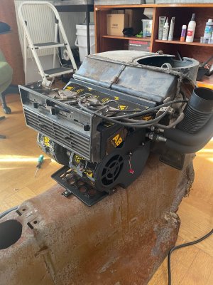
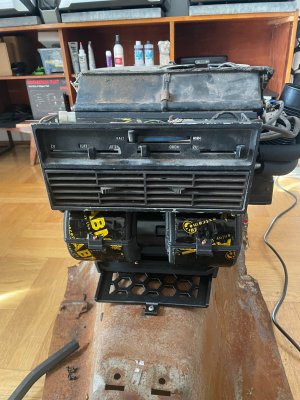
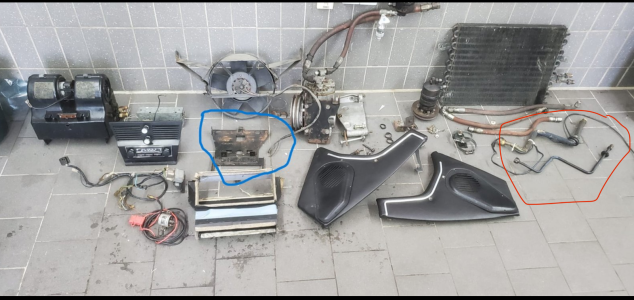
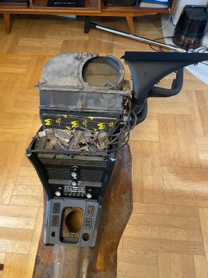
The first photo shows a complete air conditioning system removed from a BMW E9.
It took me nearly 5 years to assemble the set shown in the picture, and in the end, it turned out that one of the key components—which I had purchased believing it to be the correct one—was actually incorrect; and, in fact, completely wrong...
One of the major surprises we encountered—which caused us some trouble (thank goodness for modern technology!)—was the air conditioning evaporator base.
It might seem like a trivial detail, but it turns out to be crucial for a proper installation that won’t lead to further issues.
A key factor when installing an evaporator in a BMW E9 is its mounting height, which is determined precisely by this base.
Throughout my discussions on 3D printing—especially at the very beginning—I kept asking about the correct evaporator base.
I received various answers, but some people suggested using a base from a BMW E3—which, incidentally, is actually shown in the "blue book" (official manual) for the E9 under the air conditioning section. In fact, all the interior photos in that manual are of an E3; the center panel and the evaporator base shown there are specific to the E3 and do not fit the E9.
The center panel is—for obvious reasons—larger than the one in the E9, and the evaporator base is also significantly larger.
There were also suggestions that a base from an early-series E24 could be used. Well, perhaps, but…
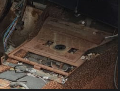
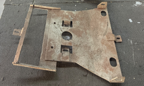
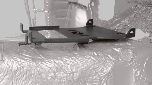
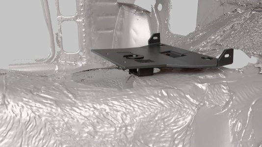
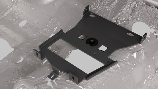
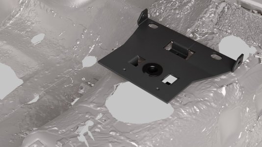
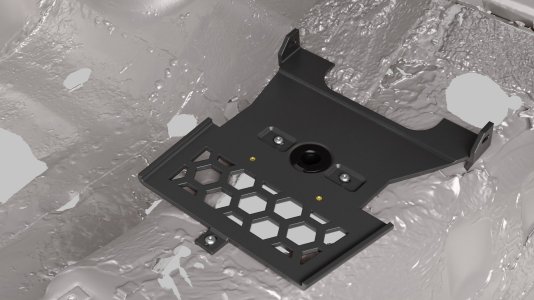
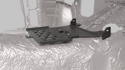
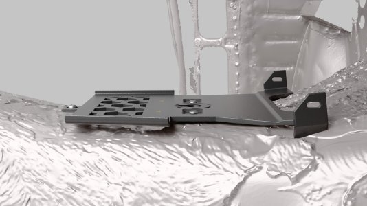
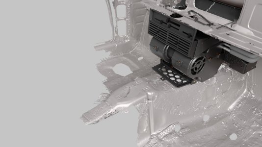
And here we get to the heart of the matter: the correct evaporator base for the E9 is the smallest of them all in terms of surface area, and, most importantly, its mounting plate sits lower than on any of the other versions.
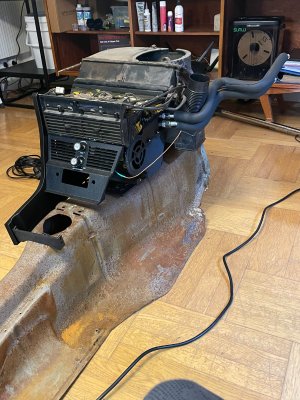
The "legs" of the evaporator base are only 1 cm high—or even less—as you can see in one of the photos below, which shows the stripped-down center tunnel of a car I once owned that had been imported from the USA. It has the correct evaporator mount for an E9 installed, and you can see exactly what the height of the front leg is in this photo. I made a mistake by not removing this mount before the sale, but at the time, I had two metal mounts that were supposed to fit an E9…
The second photo shows correct evaporator mount from my own car.
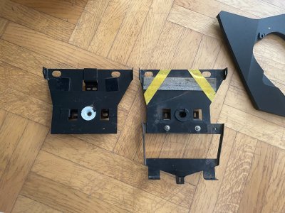
The third photo shows another correct mount.
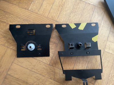
The next two photos show the evaporator bases from a BMW E3 and E24.
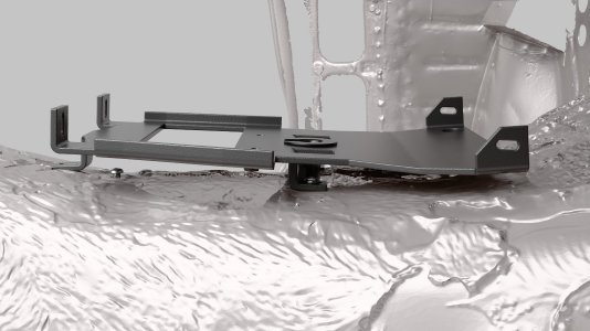
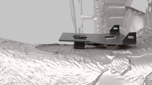
In the bases for the E3 and E24, the support legs are two centimeters high.
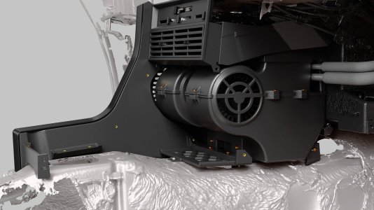
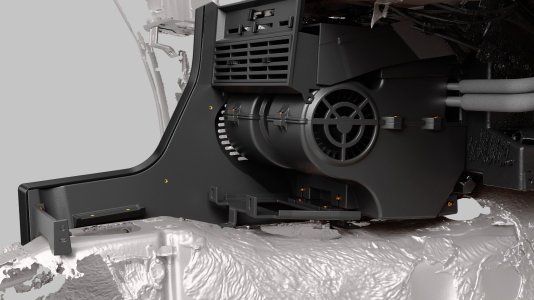
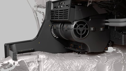
It turns out that this extra centimeter is crucial for the correct installation of the system's individual components—specifically the air duct.
If the evaporator is mounted too high, it will not align with the air duct's inlet and outlet openings.
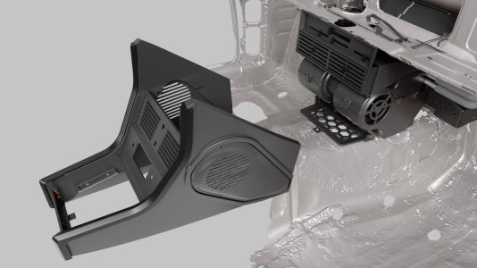
This elevation also creates issues with the proper assembly of the entire section, including the center panel and the large side panels.
The issue regarding the base came to light about three weeks ago during a trial assembly of our kit.
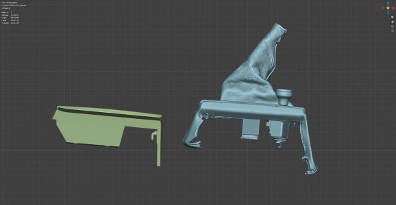
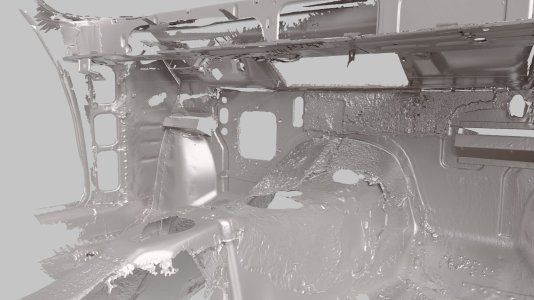
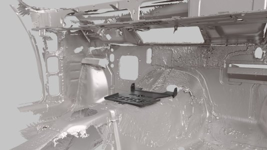
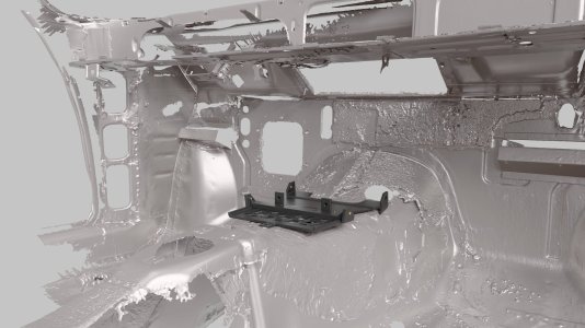
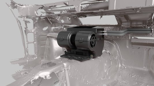
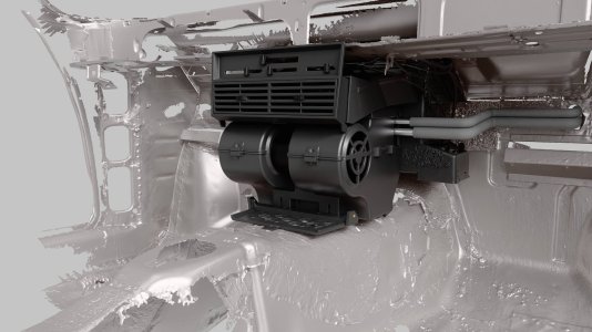
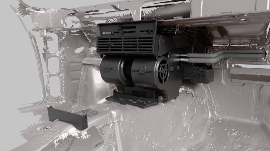
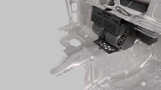
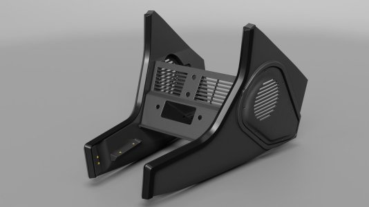
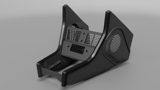
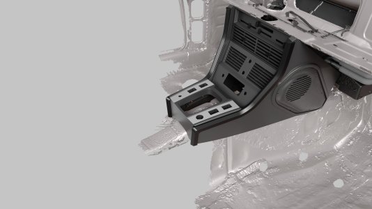
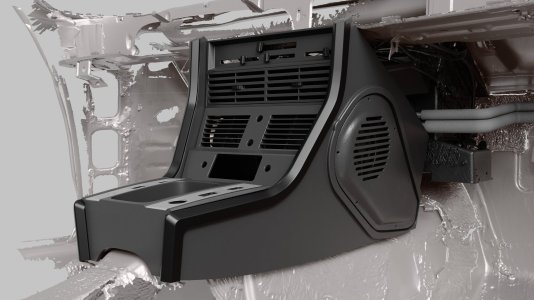
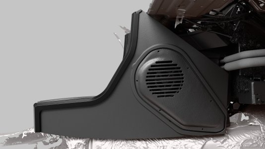
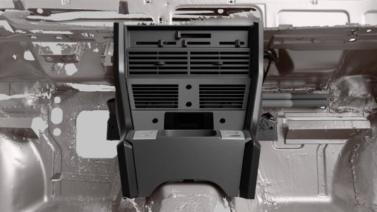
By comparing our components with an original set, we were able to verify the height differences, as shown in the attached scans and renders.
PART ONE:
While learning about the E9, I discovered that air conditioning was available as an optional extra—primarily for cars destined for the American market—and was usually installed by a BMW dealer at the customer's request.
In Europe, it was mainly in Italy and France that one could find examples equipped with an air conditioning system.
I decided that I would like to have such a system in my own car as well, since I plan to take it out mostly during the summer; I know how hot the interior can get—especially in a car with a dark-colored exterior—even after just a short time parked in direct sunlight.
I began gathering the components for the air conditioning system—a big shout-out to a few forum members who were a great help in this process.
As I collected the individual parts, I gradually familiarized myself with how air conditioning works and learned about each of its components.
The forum threads were incredibly helpful; they are a goldmine of knowledge on practically every topic related to the E9.
And this is where my long journey truly began—one that included a few surprising adventures along the way and culminated in the creation of a complete air conditioning system, designed to visually mirror the original factory setup while incorporating modern components and offering improved performance.
The first photo shows a complete air conditioning system removed from a BMW E9.
It took me nearly 5 years to assemble the set shown in the picture, and in the end, it turned out that one of the key components—which I had purchased believing it to be the correct one—was actually incorrect; and, in fact, completely wrong...
One of the major surprises we encountered—which caused us some trouble (thank goodness for modern technology!)—was the air conditioning evaporator base.
It might seem like a trivial detail, but it turns out to be crucial for a proper installation that won’t lead to further issues.
A key factor when installing an evaporator in a BMW E9 is its mounting height, which is determined precisely by this base.
Throughout my discussions on 3D printing—especially at the very beginning—I kept asking about the correct evaporator base.
I received various answers, but some people suggested using a base from a BMW E3—which, incidentally, is actually shown in the "blue book" (official manual) for the E9 under the air conditioning section. In fact, all the interior photos in that manual are of an E3; the center panel and the evaporator base shown there are specific to the E3 and do not fit the E9.
The center panel is—for obvious reasons—larger than the one in the E9, and the evaporator base is also significantly larger.
There were also suggestions that a base from an early-series E24 could be used. Well, perhaps, but…
And here we get to the heart of the matter: the correct evaporator base for the E9 is the smallest of them all in terms of surface area, and, most importantly, its mounting plate sits lower than on any of the other versions.
The "legs" of the evaporator base are only 1 cm high—or even less—as you can see in one of the photos below, which shows the stripped-down center tunnel of a car I once owned that had been imported from the USA. It has the correct evaporator mount for an E9 installed, and you can see exactly what the height of the front leg is in this photo. I made a mistake by not removing this mount before the sale, but at the time, I had two metal mounts that were supposed to fit an E9…
The second photo shows correct evaporator mount from my own car.
The third photo shows another correct mount.
The next two photos show the evaporator bases from a BMW E3 and E24.
In the bases for the E3 and E24, the support legs are two centimeters high.
It turns out that this extra centimeter is crucial for the correct installation of the system's individual components—specifically the air duct.
If the evaporator is mounted too high, it will not align with the air duct's inlet and outlet openings.
This elevation also creates issues with the proper assembly of the entire section, including the center panel and the large side panels.
The issue regarding the base came to light about three weeks ago during a trial assembly of our kit.
By comparing our components with an original set, we were able to verify the height differences, as shown in the attached scans and renders.
Attachments
-
 Zrzut ekranu 2026-10-16 o 15.20.07.png2 MB · Views: 4
 -
 Zrzut ekranu 2026-10-17 o 20.43.59.png620.1 KB · Views: 4
 -
 Zrzut ekranu 2026-10-17 o 20.34.03.png2.5 MB · Views: 4
 -
 IMG_3486.jpeg392.4 KB · Views: 4
 -
 IMG_3487.jpeg354.3 KB · Views: 4
 -
 Podstawa_01.jpg179.3 KB · Views: 4
 -
 Podstawa_02.jpg176.3 KB · Views: 4
 -
 Podstawa_04.jpg164.7 KB · Views: 4
 -
 Podstawa_05.jpg150.7 KB · Views: 4
 -
 Podstawa_07.jpg161.3 KB · Views: 4
 -
 Podstawa_08.jpg158.3 KB · Views: 4
 -
 Podstawa_09.jpg170.7 KB · Views: 4
 -
 Podstawa_03.jpg179 KB · Views: 4
 -
 Podstawa_06.jpg153.8 KB · Views: 4
 -
 Par_01.jpg170.7 KB · Views: 4
 -
 Par_02.jpg172.4 KB · Views: 3
 -
 Par_03.jpg170.1 KB · Views: 3
 -
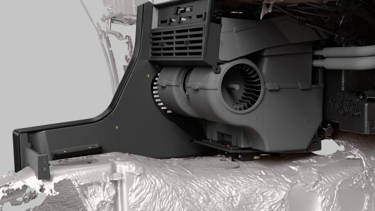 Par_04.jpg166.8 KB · Views: 3
 -
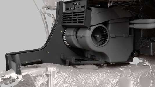 Par_05.jpg169.5 KB · Views: 4
PART TWO:
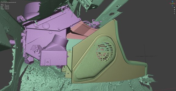
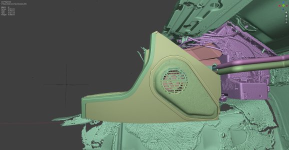
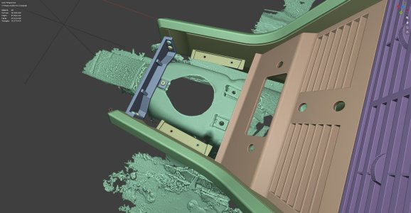
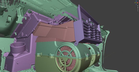
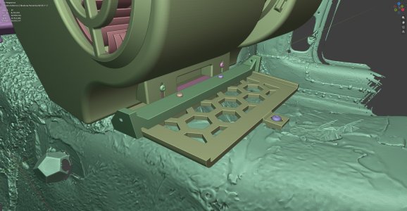
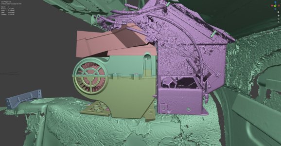
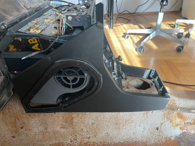
Another change I decided to implement while designing the individual components concerns the mounting method for the side panels.
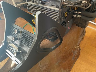
I have always been annoyed by those unsightly screws used to secure the side panels; they disrupt the overall appearance of the surface—especially around the decorative trim strip on the side panel.
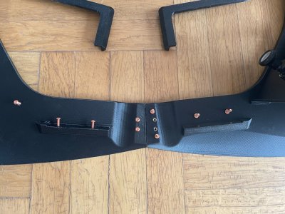
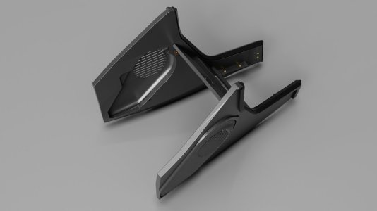
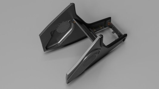
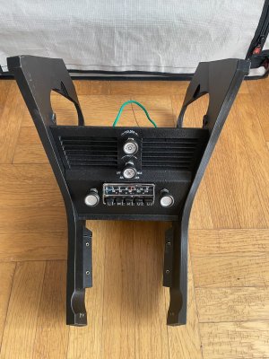
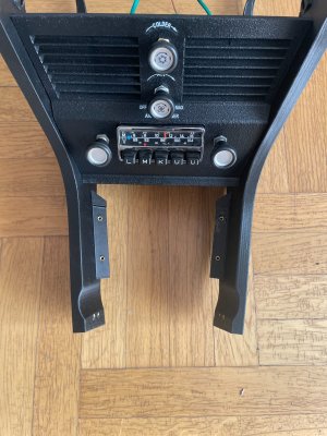
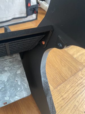
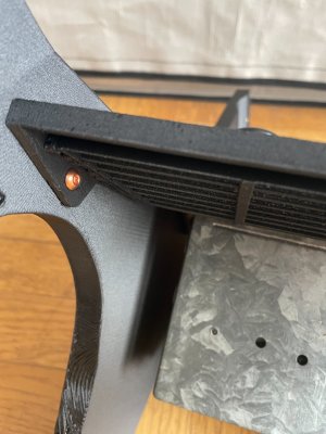
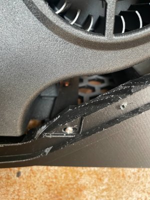
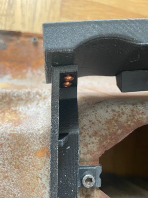
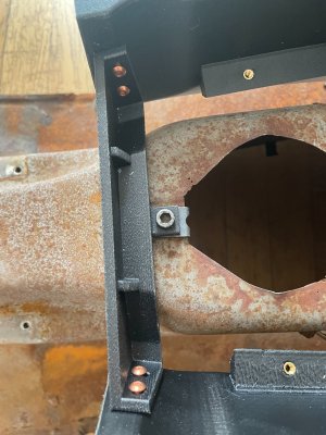
Our system uses only two attachment points, concealed beneath the edges of the panels (which feature an "elephant skin" texture), where internal connectors are secured.
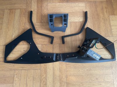
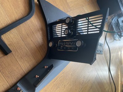
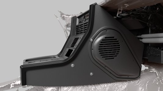
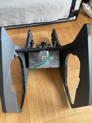
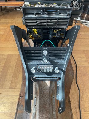
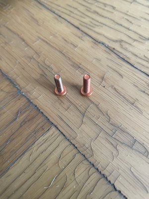
For the central panel, we replaced the original mounting method with threaded inserts positioned on the inner side of the side panels. The central panel is screwed into these inserts before the entire assembly is slid onto the evaporator unit.
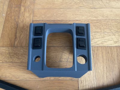
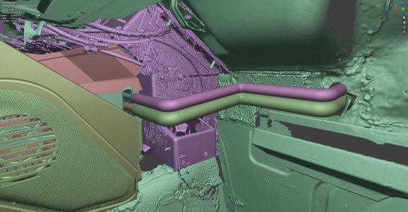
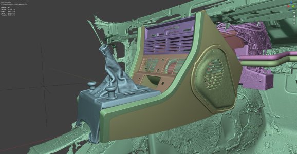
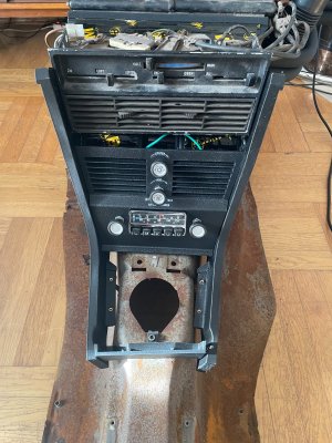
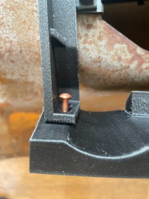
Two additional connectors serve to bind the entire structure together. One is located in the center section, attached to the evaporator base, with its ends bolted to the side panels. The second is positioned at the front of the side panels, just below the gear shifter console—a component we also redesigned to improve both its fit and its mounting method, again utilizing a threaded insert and a screw.
We have refined every component of the console assembly. After scanning the factory-original parts and reviewing a vast number of photographs of interiors equipped with air conditioning, it became clear that, in most cases, these components do not fit together precisely. This often results in uneven gaps and structural misalignments—frequently caused by the evaporator being mounted at the wrong height, often due to the use of an incorrect base.
Another change I decided to implement while designing the individual components concerns the mounting method for the side panels.
I have always been annoyed by those unsightly screws used to secure the side panels; they disrupt the overall appearance of the surface—especially around the decorative trim strip on the side panel.
Our system uses only two attachment points, concealed beneath the edges of the panels (which feature an "elephant skin" texture), where internal connectors are secured.
For the central panel, we replaced the original mounting method with threaded inserts positioned on the inner side of the side panels. The central panel is screwed into these inserts before the entire assembly is slid onto the evaporator unit.
Two additional connectors serve to bind the entire structure together. One is located in the center section, attached to the evaporator base, with its ends bolted to the side panels. The second is positioned at the front of the side panels, just below the gear shifter console—a component we also redesigned to improve both its fit and its mounting method, again utilizing a threaded insert and a screw.
We have refined every component of the console assembly. After scanning the factory-original parts and reviewing a vast number of photographs of interiors equipped with air conditioning, it became clear that, in most cases, these components do not fit together precisely. This often results in uneven gaps and structural misalignments—frequently caused by the evaporator being mounted at the wrong height, often due to the use of an incorrect base.
Attachments
-
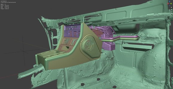 001.jpg207.8 KB · Views: 2
 -
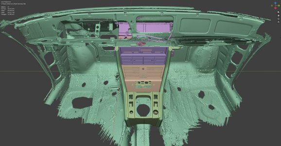 002.jpg222.7 KB · Views: 2
 -
 003.jpg194.9 KB · Views: 2
 -
 004.jpg262.5 KB · Views: 2
 -
 005.jpg184.8 KB · Views: 2
 -
 006.jpg205.5 KB · Views: 2
 -
 007.jpg163.7 KB · Views: 2
 -
 008.jpg155.3 KB · Views: 2
 -
 009.jpg188.2 KB · Views: 2
 -
 010.jpg229.6 KB · Views: 2
 -
 011.jpg109.6 KB · Views: 3
 -
 PB_02.jpg143.4 KB · Views: 4
 -
 PB_01.jpg142.3 KB · Views: 3
PART THREE:
Our entire kit is a "plug-and-play" solution for any left-hand-drive E9 body style, operating with a modern refrigerant.
We have replaced the original factory components—including the A/C condenser, condenser fan, compressor (with its mounting bracket and V-belt), receiver-drier, evaporator core, expansion valve, blower fan, temperature and fan-speed controls, and the entire electrical system—with high-quality, modern equivalents. There were no compromises made here.
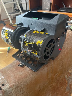
At the heart of the system is a redesigned evaporator unit, featuring a modern core, an expansion valve, and a powerful three-speed blower from Spal, which offers significantly higher airflow capacity than the original unit.
Another key component is the virtually indestructible 7-piston compressor from Sanden, which is much better suited to the E9’s engine bay than the original 5-piston version.
The system also includes an upgraded condenser and a 120W fan. This setup ensures the car can be driven with confidence even in extreme heat or heavy traffic—conditions that would typically overwhelm the original factory air conditioning system.
From my perspective, another crucial element of the system is the electrical setup.
Unfortunately, the factory-spec E9 comes equipped with an alternator that has a very low power output. With the factory-installed alternator, this car lacks sufficient electrical power…
Adding our air conditioning system—which includes three highly power-hungry components:
a compressor,
a radiator fan,
and a blower fan
will overwhelm the car’s electrical system.
If a potential buyer decides to purchase our kit, they must upgrade to a more powerful alternator.
Compatible alternators can be found in BMW E24, E28, and E34 models. The minimum recommended output is 90A.
The entire electrical setup for our system is independent and installed separately.
It includes:
A compact, sealed enclosure for relays and fuses.
Three Bosch relays, one of which features a diode (the diode serves as a protective measure).
Four fuses, including a main fuse housed in a separate protective casing located directly at the battery.
As the saying goes: "Safety first."
Another component that ensures the proper operation of the entire air conditioning system is a pressure switch (presostat). In our case, we use a highly advanced, three-function unit. It monitors compressor pressure and controls the radiator fan.
Regarding the interior components:
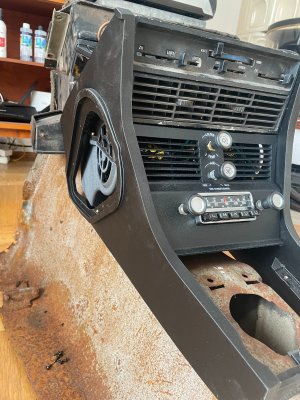
The central panel features a textured finish and offers a choice of English or German labeling. The first 15–20 units will be equipped with original control knobs; we are currently working on developing replicas.
The panel incorporates modern controls for temperature and blower fan speed.
As in the original design, the temperature control utilizes a probe positioned inside the evaporator to monitor the temperature.
Behind the central panel, mounted on our custom-designed bracket, is an evaporator unit featuring a modern core, an expansion valve, and a high-output, three-speed fan. The refrigerant lines extending from the evaporator core are shaped to match the original, allowing for direct installation.
However, we have updated the connection system to use O-rings.
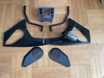
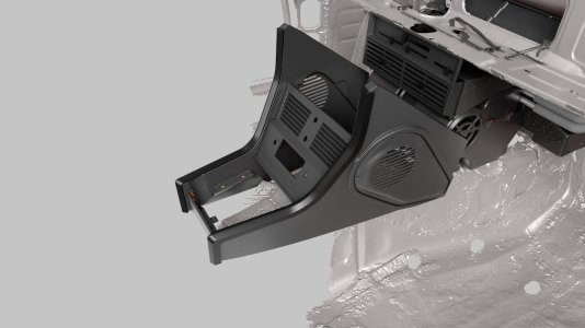
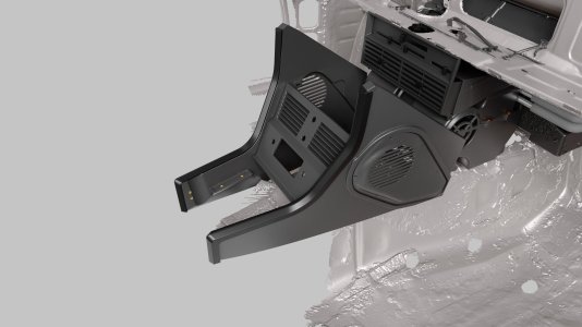
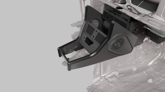
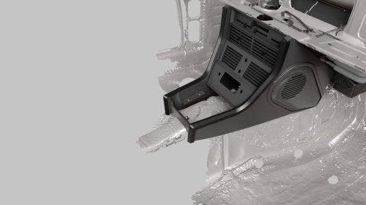
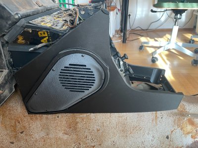
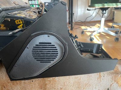
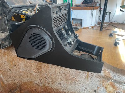
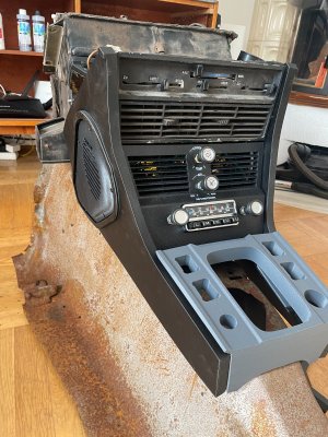
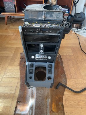
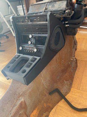
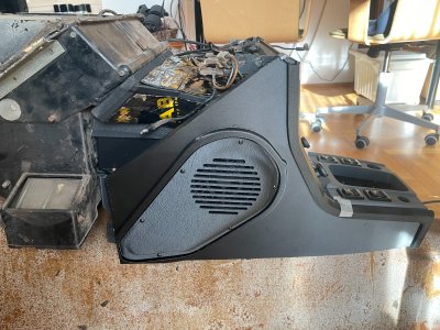
The assembly is enclosed by a structure consisting of large side panels joined by connectors and finished with smaller panels that faithfully replicate the original surface texture.
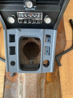
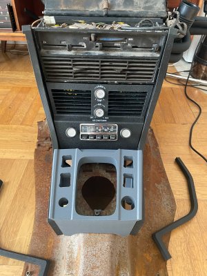
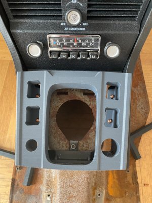
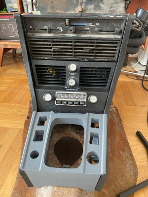
The final component of our proprietary system is a redesigned center console, with a particular focus on fitment and mounting methods.
Ultimately, the large side panels and the gear-shifter console will be upholstered.
For a complete visual effect, we recommend purchasing the decorative trim strips offered by one of our forum members; once installed, these provide a polished finishing touch, ensuring a clean, screw-free appearance that is much more aesthetically pleasing.
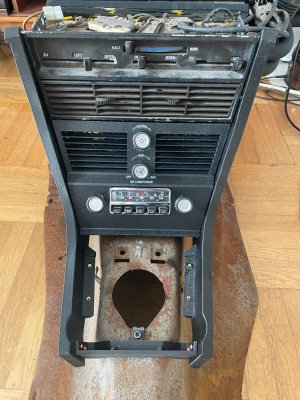
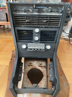
You can see the results of our more than two years of development work in the photos below. It was a long journey, fraught with many challenges, but looking at the final result, I believe it was worth it.
The entire system has been tested for assembly, leak-tightness, and functionality.
We provide a lifetime warranty on all 3D-printed components.
If something cracks or breaks, just let us know, and we will replace it with a new part.
All other components are covered by a 24-month warranty.
Below is a list of all the components that make up the complete set:
- Radiator
- Radiator fan
- Compressor, including mounting bracket and V-belt
- Receiver-drier
- Pressure switch
- Relay and fuse box
- Three relays and four fuses
- Complete evaporator unit, including expansion valve and refrigerant lines
- Evaporator base, including mounting brackets and drainage funnel
- Air duct
- Defroster vents
- Center panel, including graphics, controls, and original knobs
- Pair of large side panels
- Pair of small side panels
- Gear shifter console
- Miscellaneous installation hardware (brackets and bolts)
The price for the complete set listed above is 5,500 Euros, plus shipping costs (which will vary based on the buyer's location).
Individual components are also available for purchase separately.
Please send specific inquiries via direct message on the forum or via email to [email protected].
To mark the launch of our retro air conditioning system, we are hosting a contest with some exciting prizes. As an added incentive, the grand prize is our complete air conditioning system!
You can find the link to the contest thread below:
For the duration of the contest, the set is available at a promotional price of 5,000 Euros.
This price will remain in effect throughout the entire duration of the contest (linked above).
The contest runs for one month, starting today.
If you have any questions, please feel free to ask—I will do my best to answer them! As an interesting side note, we are currently working on a complete interior sound system for the E9…
Finally, a huge thank you to:
- DON
- Thomas
- DLC
- BMW3.0CSI
- Blinkling
- The Cracow Company "Frosti"– for assembling and testing the core and its components, as well as providing technical consultation.
- Siraya Tech
And to my Polish team—without You, this project would never have gotten off the ground, let alone succeeded:
Graphic Designer – Adrian
Scanner – Sebastian
Technical aspects of 3D printing – Artur
Mental and financial support – Lukas
Thank You all, Gentlemen!!!
One project delivered—time for the next ones.
More details coming soon…
Our entire kit is a "plug-and-play" solution for any left-hand-drive E9 body style, operating with a modern refrigerant.
We have replaced the original factory components—including the A/C condenser, condenser fan, compressor (with its mounting bracket and V-belt), receiver-drier, evaporator core, expansion valve, blower fan, temperature and fan-speed controls, and the entire electrical system—with high-quality, modern equivalents. There were no compromises made here.
At the heart of the system is a redesigned evaporator unit, featuring a modern core, an expansion valve, and a powerful three-speed blower from Spal, which offers significantly higher airflow capacity than the original unit.
Another key component is the virtually indestructible 7-piston compressor from Sanden, which is much better suited to the E9’s engine bay than the original 5-piston version.
The system also includes an upgraded condenser and a 120W fan. This setup ensures the car can be driven with confidence even in extreme heat or heavy traffic—conditions that would typically overwhelm the original factory air conditioning system.
From my perspective, another crucial element of the system is the electrical setup.
Unfortunately, the factory-spec E9 comes equipped with an alternator that has a very low power output. With the factory-installed alternator, this car lacks sufficient electrical power…
Adding our air conditioning system—which includes three highly power-hungry components:
a compressor,
a radiator fan,
and a blower fan
will overwhelm the car’s electrical system.
If a potential buyer decides to purchase our kit, they must upgrade to a more powerful alternator.
Compatible alternators can be found in BMW E24, E28, and E34 models. The minimum recommended output is 90A.
The entire electrical setup for our system is independent and installed separately.
It includes:
A compact, sealed enclosure for relays and fuses.
Three Bosch relays, one of which features a diode (the diode serves as a protective measure).
Four fuses, including a main fuse housed in a separate protective casing located directly at the battery.
As the saying goes: "Safety first."
Another component that ensures the proper operation of the entire air conditioning system is a pressure switch (presostat). In our case, we use a highly advanced, three-function unit. It monitors compressor pressure and controls the radiator fan.
Regarding the interior components:
The central panel features a textured finish and offers a choice of English or German labeling. The first 15–20 units will be equipped with original control knobs; we are currently working on developing replicas.
The panel incorporates modern controls for temperature and blower fan speed.
As in the original design, the temperature control utilizes a probe positioned inside the evaporator to monitor the temperature.
Behind the central panel, mounted on our custom-designed bracket, is an evaporator unit featuring a modern core, an expansion valve, and a high-output, three-speed fan. The refrigerant lines extending from the evaporator core are shaped to match the original, allowing for direct installation.
However, we have updated the connection system to use O-rings.
The assembly is enclosed by a structure consisting of large side panels joined by connectors and finished with smaller panels that faithfully replicate the original surface texture.
The final component of our proprietary system is a redesigned center console, with a particular focus on fitment and mounting methods.
Ultimately, the large side panels and the gear-shifter console will be upholstered.
For a complete visual effect, we recommend purchasing the decorative trim strips offered by one of our forum members; once installed, these provide a polished finishing touch, ensuring a clean, screw-free appearance that is much more aesthetically pleasing.
You can see the results of our more than two years of development work in the photos below. It was a long journey, fraught with many challenges, but looking at the final result, I believe it was worth it.
The entire system has been tested for assembly, leak-tightness, and functionality.
We provide a lifetime warranty on all 3D-printed components.
If something cracks or breaks, just let us know, and we will replace it with a new part.
All other components are covered by a 24-month warranty.
Below is a list of all the components that make up the complete set:
- Radiator
- Radiator fan
- Compressor, including mounting bracket and V-belt
- Receiver-drier
- Pressure switch
- Relay and fuse box
- Three relays and four fuses
- Complete evaporator unit, including expansion valve and refrigerant lines
- Evaporator base, including mounting brackets and drainage funnel
- Air duct
- Defroster vents
- Center panel, including graphics, controls, and original knobs
- Pair of large side panels
- Pair of small side panels
- Gear shifter console
- Miscellaneous installation hardware (brackets and bolts)
The price for the complete set listed above is 5,500 Euros, plus shipping costs (which will vary based on the buyer's location).
Individual components are also available for purchase separately.
Please send specific inquiries via direct message on the forum or via email to [email protected].
To mark the launch of our retro air conditioning system, we are hosting a contest with some exciting prizes. As an added incentive, the grand prize is our complete air conditioning system!
You can find the link to the contest thread below:

Hello everyone.
In light of the presentation of our air conditioning system for the BMW E9, we are launching a contest for the most interesting photo featuring a BMW E9—though this time, the car shouldn't be the main focus, but rather a part of the background…
That’s right: this time, it’s not about the best-looking, finest, or most magnificent car; it’s about an interesting or intriguing localizations —a unique background.
Gentlemen—creativity is what counts.
It is the primary criterion for determining the winner.
Below, you’ll find a few examples that illustrate our vision and the...
In light of the presentation of our air conditioning system for the BMW E9, we are launching a contest for the most interesting photo featuring a BMW E9—though this time, the car shouldn't be the main focus, but rather a part of the background…
That’s right: this time, it’s not about the best-looking, finest, or most magnificent car; it’s about an interesting or intriguing localizations —a unique background.
Gentlemen—creativity is what counts.
It is the primary criterion for determining the winner.
Below, you’ll find a few examples that illustrate our vision and the...
For the duration of the contest, the set is available at a promotional price of 5,000 Euros.
This price will remain in effect throughout the entire duration of the contest (linked above).
The contest runs for one month, starting today.
If you have any questions, please feel free to ask—I will do my best to answer them! As an interesting side note, we are currently working on a complete interior sound system for the E9…
Finally, a huge thank you to:
- DON
- Thomas
- DLC
- BMW3.0CSI
- Blinkling
- The Cracow Company "Frosti"– for assembling and testing the core and its components, as well as providing technical consultation.
- Siraya Tech
And to my Polish team—without You, this project would never have gotten off the ground, let alone succeeded:
Graphic Designer – Adrian
Scanner – Sebastian
Technical aspects of 3D printing – Artur
Mental and financial support – Lukas
Thank You all, Gentlemen!!!
One project delivered—time for the next ones.
More details coming soon…
Attachments
-
 Render_12.jpg189.8 KB · Views: 0
 -
 Render_11.jpg191.9 KB · Views: 0
 -
 Render_10.jpg192 KB · Views: 0
 -
 Render_09.jpg192.4 KB · Views: 0
 -
 Render_08.jpg185.5 KB · Views: 0
 -
 Render_06.jpg183.3 KB · Views: 0
 -
 Render_05.jpg184 KB · Views: 0
 -
 Render_17.jpg142.7 KB · Views: 1
 -
 Render_16.jpg60.2 KB · Views: 1
 -
 Render_15.jpg62.5 KB · Views: 1
 -
 Render_14.jpg72.7 KB · Views: 1
 -
 Render_13.jpg73.1 KB · Views: 1
 -
 Render_17.jpg142.7 KB · Views: 1
 -
 Render_18.jpg165.2 KB · Views: 1
 -
 Render_20.jpg133.2 KB · Views: 1
 -
 Render_21.jpg132.1 KB · Views: 1
 -
 Render_22.jpg130.7 KB · Views: 1
 -
 Render_23.jpg131.1 KB · Views: 1
 -
 Render_24.jpg133 KB · Views: 0
 -
 Wizka_1.jpg172.8 KB · Views: 0
 -
 Wizka_2.jpg154.8 KB · Views: 0
 -
 Wizka_3.jpg222.6 KB · Views: 0
 -
 IMG_3524.jpeg425.2 KB · Views: 0
 -
 IMG_3525.jpeg360.4 KB · Views: 0
 -
 IMG_3526.jpeg236.1 KB · Views: 0
 -
 IMG_3527.jpeg257.8 KB · Views: 0
 -
 IMG_3528.jpeg418 KB · Views: 0
 -
 IMG_3529.jpeg444.8 KB · Views: 0
 -
 IMG_3530.jpeg332.1 KB · Views: 0
 -
 IMG_3531.jpeg434 KB · Views: 0
 -
 IMG_3532.jpeg386.9 KB · Views: 0
 -
 IMG_3533.jpeg435.1 KB · Views: 0
 -
 IMG_3534.jpeg288.7 KB · Views: 0
 -
 IMG_3535.jpeg268.5 KB · Views: 0
 -
 IMG_3536.jpeg256.6 KB · Views: 0
 -
 IMG_3537.jpeg337.5 KB · Views: 0
 -
 IMG_3538.jpeg436.3 KB · Views: 0
 -
 IMG_3539.jpeg428.3 KB · Views: 0
 -
 IMG_3540.jpeg425 KB · Views: 0
 -
 IMG_3541.jpeg429.9 KB · Views: 1
Last edited:
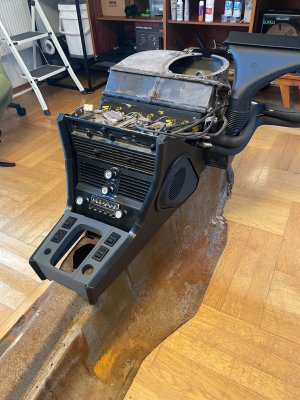
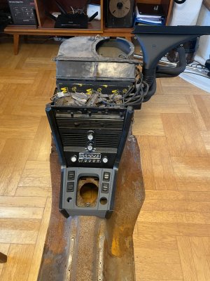
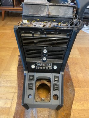
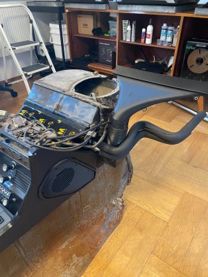
A few missing photos from the installation:
Attachments
-
 IMG_3542.jpeg414.1 KB · Views: 1
 -
 IMG_3543.jpeg450.8 KB · Views: 1
 -
 IMG_3544.jpeg351.3 KB · Views: 1
 -
 IMG_3545.jpeg420.8 KB · Views: 1
 -
 IMG_3546.jpeg408.1 KB · Views: 1
 -
 IMG_3547.jpeg401.1 KB · Views: 1
 -
 IMG_3548.jpeg436.1 KB · Views: 1
 -
 IMG_3549.jpeg377.6 KB · Views: 1
 -
 IMG_3550.jpeg379.8 KB · Views: 1
 -
 IMG_3551.jpeg464.1 KB · Views: 1
 -
 IMG_3571.jpeg407.1 KB · Views: 1
 -
 IMG_3572.jpeg382.2 KB · Views: 1
 -
 IMG_3573.jpeg380.2 KB · Views: 1
 -
 IMG_3574.jpeg369.3 KB · Views: 1
 -
 IMG_3575.jpeg387.4 KB · Views: 1