72 3.0 CS 2240344 Restoration

Those are extremely cool. This is definitely going to be part of car restoration into the future as parts become more and more scarce and interest in creating them wains.

Love the manifolds in particular… very clean looking.
 
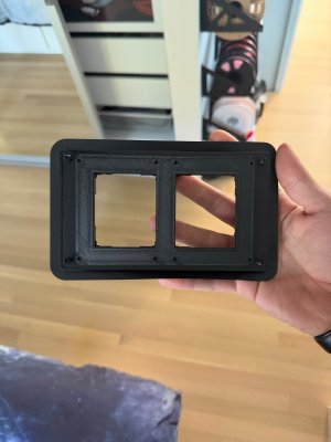
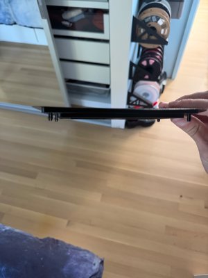
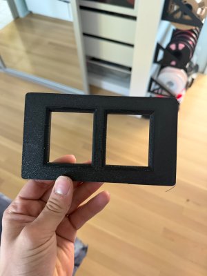
Here are the prints of the speaker holder for the planar speakers. I’m out of town on a 5-day cycling ride in Bend but will check the fit as soon as I get home. Pictures courtesy of my son. Nice job Scott!

Realize I should have posted this in the speaker discussion thread. No way to delete this one so I’ll copy the post there
 

Attachments

  • IMG_2926.jpeg
    IMG_2926.jpeg
    366.4 KB · Views: 35
  • IMG_2925.jpeg
    IMG_2925.jpeg
    313.1 KB · Views: 34
  • IMG_2927.jpeg
    IMG_2927.jpeg
    381.7 KB · Views: 32
Here are the prints of the speaker holder for the planar speakers. I’m out of town on a 5-day cycling ride in Bend but will check the fit as soon as I get home. Pictures courtesy of my son. Nice job Scott!

Realize I should have posted this in the speaker discussion thread. No way to delete this one so I’ll copy the post there
Unfortunately, I think the pins are not strong enough. LMK what you think once you work with it. I redesigned it to use a two-piece assembly. The baffle is thinner and mounts tot he dash panel with blind nuts, and the grille attaches with a thin plate using the same basic pins as the original
 
Wow that looks amazing!!! Nice job. I assume that they also did some reworking of the fill so that it’s not 50-year-old hay?
 
On @e9Leveque's thread we have been discussing retro fit oil pressure and voltage gauges by replacing the clock.

I located a left side fuel/temp gauge from an E9. I also bought a 928 oil pressure and voltage gauge (at least the innards). Both arrived yesterday. Unfortunately, the 928 gauge was damaged in shipping (the needles are badly bent).

I decided to open up the E9 gauge. Turned out to be dead simple. each meter movement is held in place with only two screws on the back side. When I pulled them out I realized that the gauge faces are simply screened on to small face plates that screw onto the meter structure...

So rather than mess with fitting the 928 movements into the E9 case, I am just going to create new back plates and have them printed or silk screened. The meter movements seem to be basically the same (ultimately just a galvanometer), so with some calibration I should be good to go with the new faceplates. This will also allow me to better match the fonts and colors for the gauges, and avoid having to paint the needles.

IMG_6323.jpg
IMG_6325.jpg

It also turns out that with a bit of jiggling, you can remove the shrouds that hold the warning lights. So I may either replace these with appropriate lights for oil and voltage, or just block them off.

IMG_6326.jpg


And notionally, here are the revised face plates...The font is Eurostile

Screenshot 2026-07-18 at 11.27.50 AM.png


And here are the actual faceplates. Think I am just going to make some decals for these with the new layout above.

IMG_6331.jpg
 
Last edited:
Cool Scott… that is a neat project. I wish there was a simple way to remove the glass on the gauges… I was too chicken to do the pry and bend thing… mine are filthy inside.
 
Cool Scott… that is a neat project. I wish there was a simple way to remove the glass on the gauges… I was too chicken to do the pry and bend thing… mine are filthy inside.
You might be able to get to it from the back. On the side gauges, the meters come out easily, and then you could probably swab inside with bent Q-tip and alcohol
 
Last edited:
Wow just wow. Amazing work. This is going to look amazing. And after I spent all this time and effort adding in three extra gauges below the radio! Very cool and looking forward to seeing the end product. I wonder what else one could do with the warning lights since they aren’t needed here. There has to be something else that could be put in their place. I guess if you added an AFR gauge maybe could have old-school red digit readout that fit in there. Needs to be something without a needle since you don’t have room for any mechanism
 
Wow just wow. Amazing work. This is going to look amazing. And after I spent all this time and effort adding in three extra gauges below the radio! Very cool and looking forward to seeing the end product. I wonder what else one could do with the warning lights since they aren’t needed here. There has to be something else that could be put in their place. I guess if you added an AFR gauge maybe could have old-school red digit readout that fit in there. Needs to be something without a needle since you don’t have room for any mechanism
Not sure I need any additional lights. I may hook up the upper ones in parallel with the oil and alt lights on the left, since those are the gauges that will be there
 
Not sure I need any additional lights. I may hook up the upper ones in parallel with the oil and alt lights on the left, since those are the gauges that will be there
Alternatively I may hook up a simple battery state light I.e. low volts, and maybe move oil pressure to the oil gauge side and put in a hi temp warning light. So left to right the lights would be temp, alt, oil press, low volts
 
OK, so After spending a nice afternoon degreasing my subframes (oh joy!) in preparation for welding in the rear camber and toe adjustment plates tomorrow, I took some detailed measurements of the meter faces, and drew some scale meter decals. These look pretty good, so I think I'll get some printed and see how they come out.

Screenshot 2026-07-18 at 10.13.58 PM.png
 
Last edited:
Good morning, Scott

Would you consider a group buy if you have these printed? I'm following in your footsteps.

Thanks

David
Yeah, I might do that. Or I'll post the artwork and folks can buy their own. Cost for the first run of 10 was $25.

But there are a lot of variables, so let's see how these come out first...
 
Yes I’d be in for a set for future reworking of my dash. Not now!
Good morning, Scott

Would you consider a group buy if you have these printed? I'm following in your footsteps.

Thanks

David
Y'all have to start by finding a good left hand gauge for an E9. These run between $180-$300 on eBay.

The stickers (assuming they work properly) are super cheap. I ordered a vinyl sticker with both gauge faces on it. It has a satin finish (supposedly). I plan to carefully cut out the gauge faces from the sticker and then apply it to the gauge dial plate. I am pretty sure, as most things like this go, there will be a few iterations...

The next trick will be to calibrate the gauges so they read properly. I think, based on JC's work on his oil pressure gauge (the graph of resistance vs pressure), that I can simulate the oil sender using a variable resistor, and use that to calibrate the gauge. Calibrating the gauge is an electronics exercise. The gauge itself is just a current meter (a galvanometer). One side is connected to 12 volts and the other goes through some internal resistors and then to the sender. As the resistance of the sender changes, the current changes causing the meter to change position. Adding resistance to the sender line will move the meter pointer up. Since you can't reduce resistance, to move the meter down you add parallel resistance to the sender. That will also, however change the scale, so this may require changing the internal resistance inside the meter.

The volt meter will be somewhat different since there is no sender. There, the meter is attached to 12 volts and the other end is grounded through a fixed resistor. I'll adjust that resistor (and possibly the internal ones) so that the meter accurately reads the voltage on the 12 volt line.

I am a bit curious about the innards of the meters. They have a resistor, but they also appear to have a coil of wire. I am not sure if that is just a fine tuned resistor, or serves some other function. I guess I'll find out!
 
Back
Top