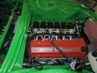
72 Restomod clubracer build

Thanks Gary
here are some more picture of the Chassis harness install

013.JPG


Mounted the Kill switch solenoid and circuit breaker . I prefer this style of kill switch as to just the typical mechanical switch that most use , this is more of a professional style deal and has toggle switch's that operate this large solenoid that cuts power .

018.JPG


Battery location , next to the solenoid , and a view of the harness layout

019.JPG


View of harness into the switch panel

020.JPG
 
Its been slow progress this summer, between the heat in the shop and I had bicycle wreck I haven't gotten much done lately

but here's a few update's

023.JPG


the dash actually powered up after the chassis harness install

024.JPG


025.JPG


001.JPG


the oil lines are done once and for all and we started laying out the fuel lines

002.JPG


close up modified fuel rail to take AN lines

003.JPG


fuel pressure reg. mounted
 
001.JPG


taillights installed with center trim piece

007.JPG


working Brake lights , yeah !

004.JPG


oil lines totally finished now, seen going into remote filter, also note oil gauge pressure switch

006.JPG


oil lines going though front cowl to oil cooler mounted in front of radiator
 
010.JPG


009.JPG


getting close to finishing up the coolant system. since the air box will take up all of the space where the rev. usually resides , I relocated it to the pass side towards the front. Steven made this quite nice bracket to hold it in place
 
work on putting the fuel cell together.

026.JPG


the bladder sitting onside an Aluminum can

Sg6P9SdZfh60YbpyIsphVMkLIoEbUnDiMgmOSHShvqk=w829-


the ATL "black box" . A box with trap doors with high pressure pump in the center so you don't get fuel starvation issues

004.JPG


close up of the inside of the black box

Ro0zGVn0QF1TT2PjqbPgkZ-jbs3BLGmg0fWqHhqm1X0=w241-h180-p-no


the foam baffling to help with fuel surge and holds the black box/surge tank in place

009.JPG


Black box inside the bladder

015.JPG


install the fill plate after modifying it for the electric pump and addition fuel line's

013.JPG


014.JPG


building some "AN lines" for the fuel system

016.JPG
 
Knocked out another project today, got the rest of the Diff system done. Made some brackets to hang the diff pump and diff cooler assembly. Mounted those parts and made up the lines to plumb it. wired it and done

001.JPG


diff pump and bracket

002.JPG


diff cooler and fan assembly

003.JPG


Diff pump mounted in place

004.JPG


cooler and fan assembly

005.JPG


view of system for underneath

006.JPG


making the feed and return lines

007.JPG


system plumbed up
 
Finishing up the fuel system plumbing

010.JPG


lines in and out of the fuel pressure regulator

013.JPG


lines down the car

014.JPG


018.JPG


019.JPG


002.JPG
 
Brendan, its looking amazing ... looking forward to seeing this beauty run. i need to come see it sometime soon

scott
 
Thanks guys !
It may be to beautiful too you guys to race , but its got way too many trick race parts not to race it !

Been busy knocking out the tedious stuff. mounted the brake bais knob and fire pull into the switch panel

001.JPG
 
work on the fire system

011.JPG


003.JPG


Fire bottle mounted and the lines getting laid out and mounted

001.JPG


mounted nozzle in engine compartment
 
005.JPG


pulled the dash back out and mounted the final fire nozzle aimed at the driver
also planned out the final bit of wiring that needs to be done , and mounting of brake bais and other cables . so when the dash goes back in that will be the last time hopefully. then we can install the front windshield

speaking of windshields finally after wrestling with lexan for months and months Ive actually made headway and even gotten the rear one installed.
turned out to be a lot more difficult than I planned. cutting them to shape and size was easy but installing them with out the curves proved to be impossible , We tried heating them with heat guns to get the curve in the lexan but the piece is just to big for that to retrain enough heat to shape it with out getting concentrated and bubling the lexan . eventually I had to take it somewhere with an oven big enough to form the piece . I found a place In Decatur near where I live that would accommodate me . they used the old glass windshield as a mold and laid my lexan in it in the oven and BAM we got light weight windshields front and rear ( the sides I can do alone )

001.JPG


cutting out the windshield

q3bKcZyBOh4Wa8b0-XH2EyU5GiC_aMEEWWxVlkHnd3g=w271-h203-p-no


009.JPG


trying to get it installed without the curves almost successful but the curves were to severe and never could get the last little bit in

009.JPG


curved pieces ready for install

004.JPG


002.JPG


Rear piece installed , still has protective cover on it though
 
001.JPG


002.JPG


Breather installed , breather catch can , made the breather hose and had the valve cover modified to fit an AN fitting on it . Also note the engine harness taking shape and getting installed . Bulkhead connectors installed to the left of the headers


002.JPG
 
more slow tedious work . finally got most of the engine harness and electronics' mounted and installed. Had a mil spec engine harness built from scratch . Today we got the chassis harness integrated with the engine electronics . A huge, huge step forward , getting me that much closer to firing it up. was able to turn on the engine fan and run the fuel pump. We used Mil spec Bulk head connector's everywhere to keep the cabin sealed and to make parts of the harness easily detachable for servicing .

007.JPG


starting to mount the engine electronics' on a plate , relays and fuses on the top left, ECU on the top right which the two ignition ignitiors . right now looking like one hot mess

006.JPG


made up a plate to mount it all on and giving it some paint

007.JPG


remounting the components

008.JPG


sorting out the lay out of the harness, notice the holes drilled in the firewall for the bulkhead connectors

002.JPG


004.JPG


installed bulkhead for some the electronics on the driver side , and the battery power line to the starter and alt.

005.JPG


011.JPG


bulkhead 's coming together along with getting the harness's mounted

010.JPG


bulkheads from the engine side, top one is for harness going to most engine control sensors, while the middle one goes to the coils, and the bottom one is for the gauge sensors

013.JPG


back into the switch panel again, and removed the dash , installed two more toggles , one for the fuel pump and the engine fan , I wanted to be able to operate those items myself but the ECU will turn both on as needed as well

014.JPG


the birds nest getting cleaned up and mounted, the intregration between the engine electronics and the switch panel

016.JPG


019.JPG


Just a few loose ends left to tie up , but the wiring in the car is basically done !!
 
got the O2 sensor and wiring installed. Its an innovate wideband . the damn thing comes with an unbelievable extra amount of cord . If I installed it as it came it would have looked messy at best . So we modified the wiring to the thing. Cut out most of the extra cord and installed a bulkhead connector so I could keep the cabin sealed esp. being that this is going to the exhaust system.

006.JPG


the O2 sensor itself

009.JPG


installed underneath the car and the bulkhead

022.JPG


the O2 wiring to the ECU
 
Back
Top