72 Restomod clubracer build

bdigel

Well-Known Member
Messages
534
Reaction score
318
Location
Atlanta
Hi Gary

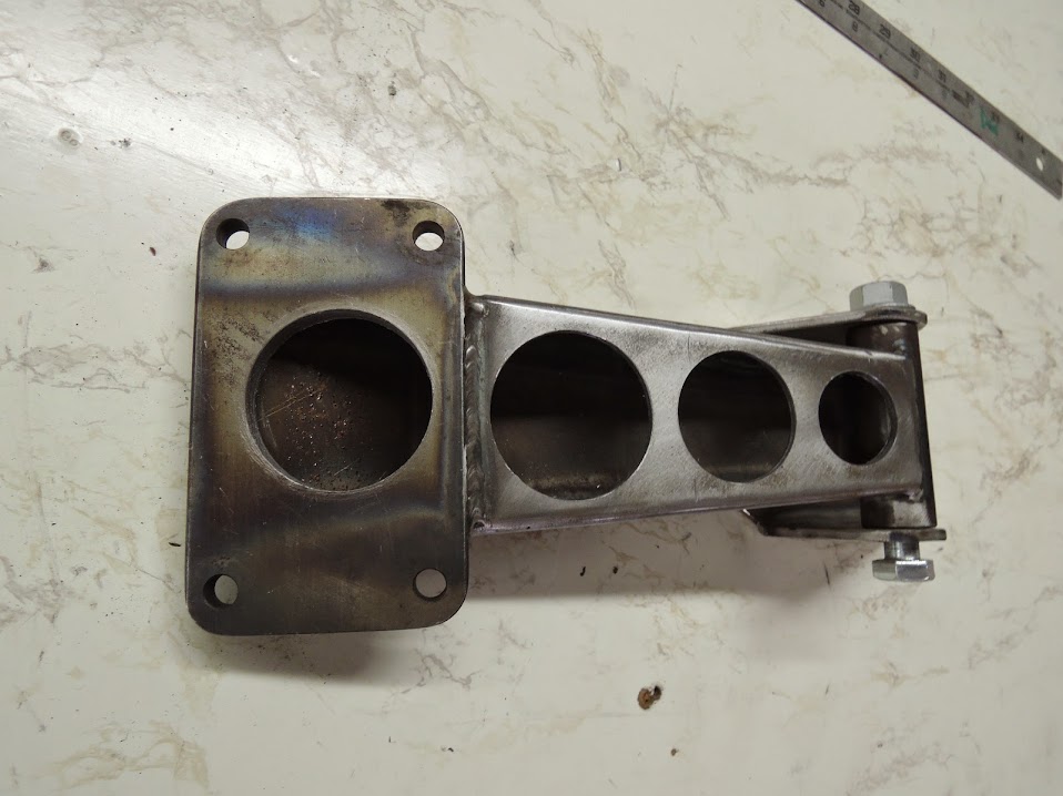
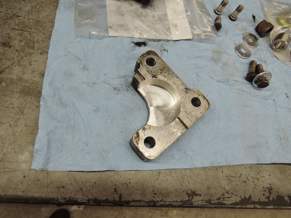
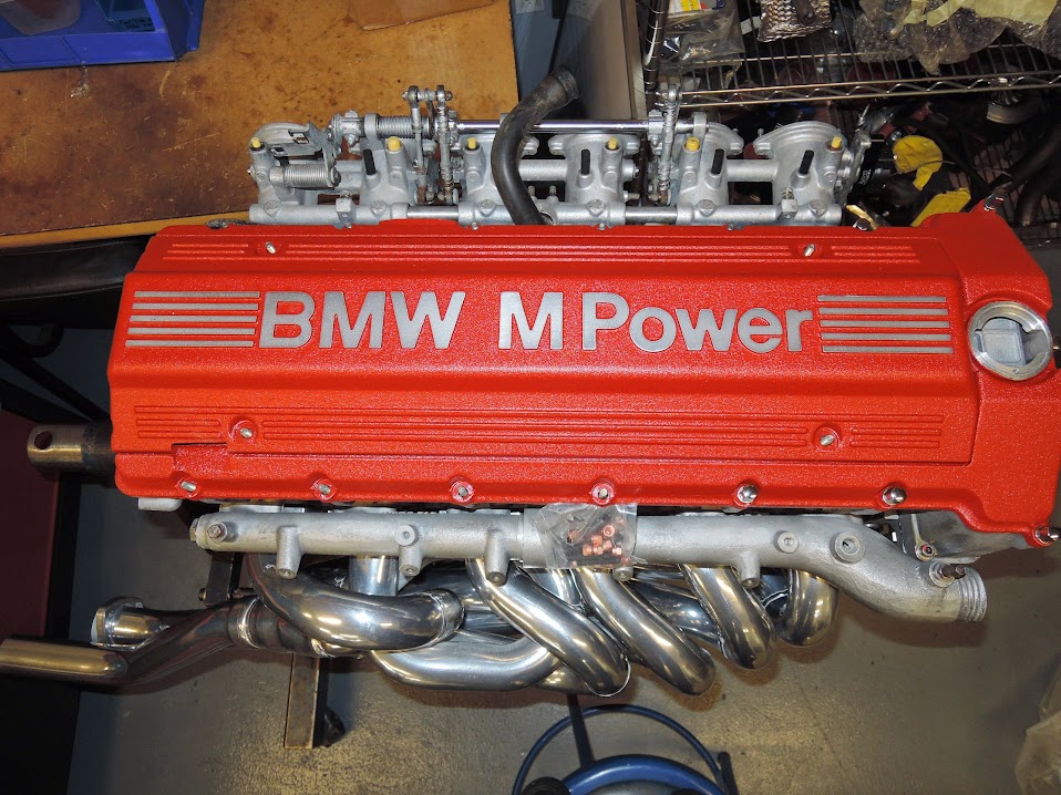
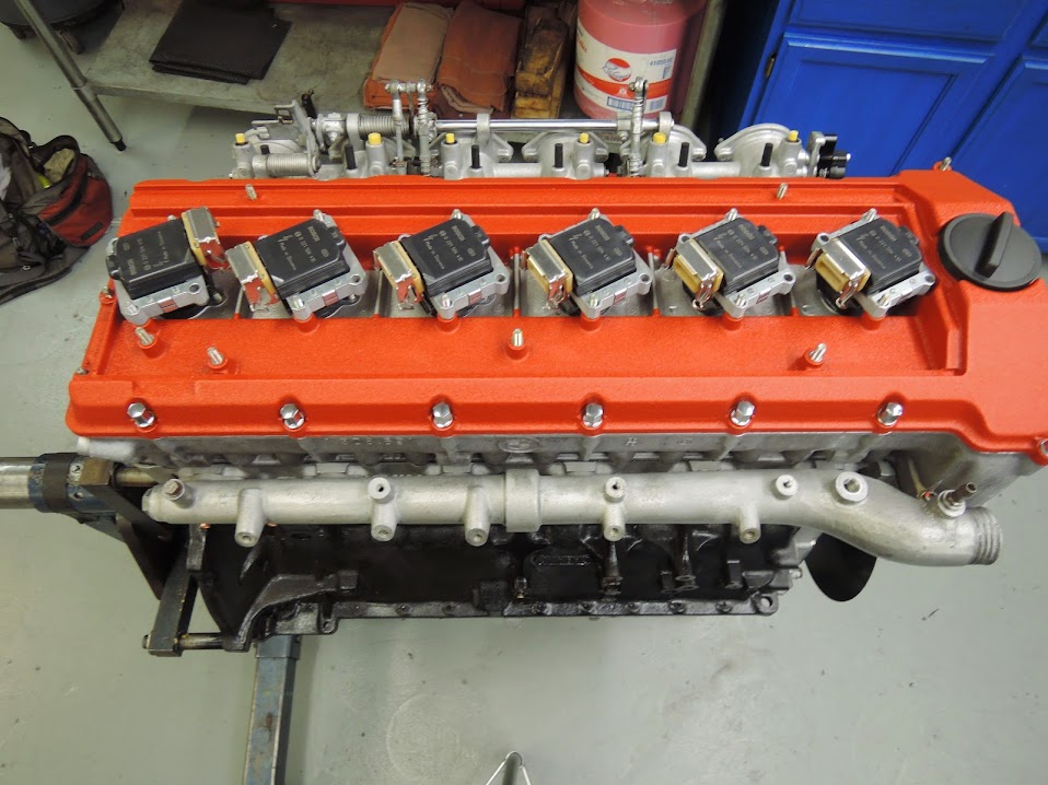
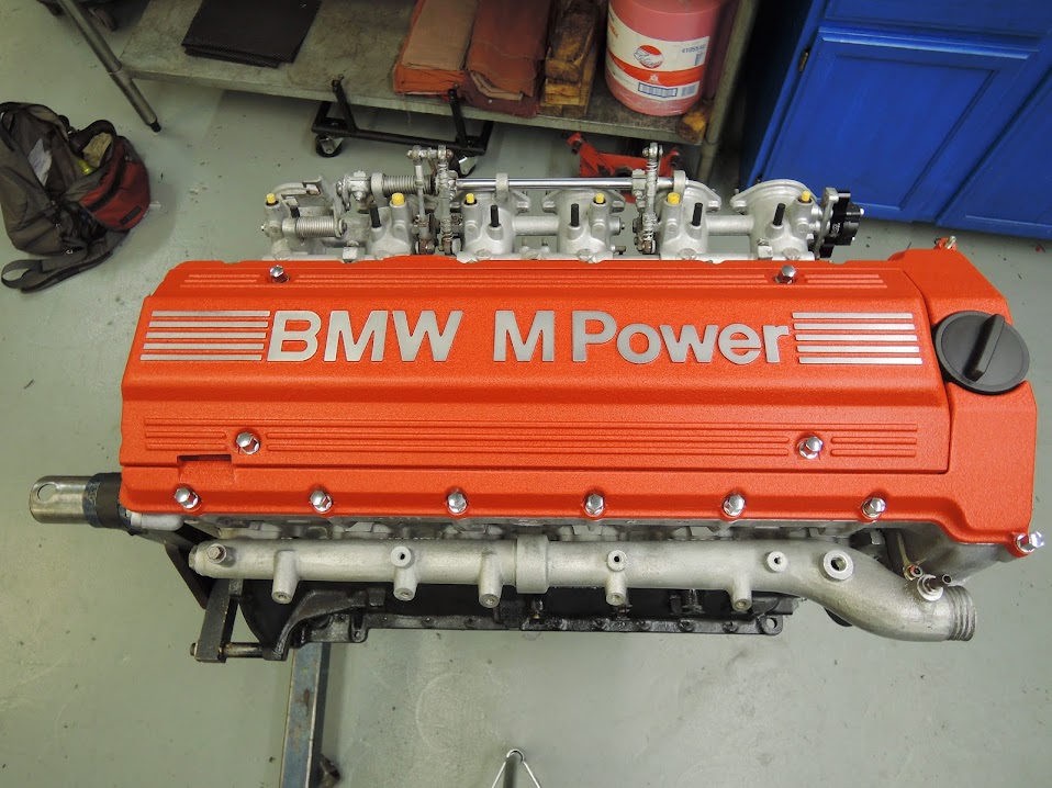
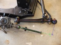
to answer your questions , 1st no that sensor will not work with your early motronic , your motronic just looks for idle and WFO , later stuff needs to see partial loads , that sensor is from an s54 and an adapter plate to fit on the s38 throttles
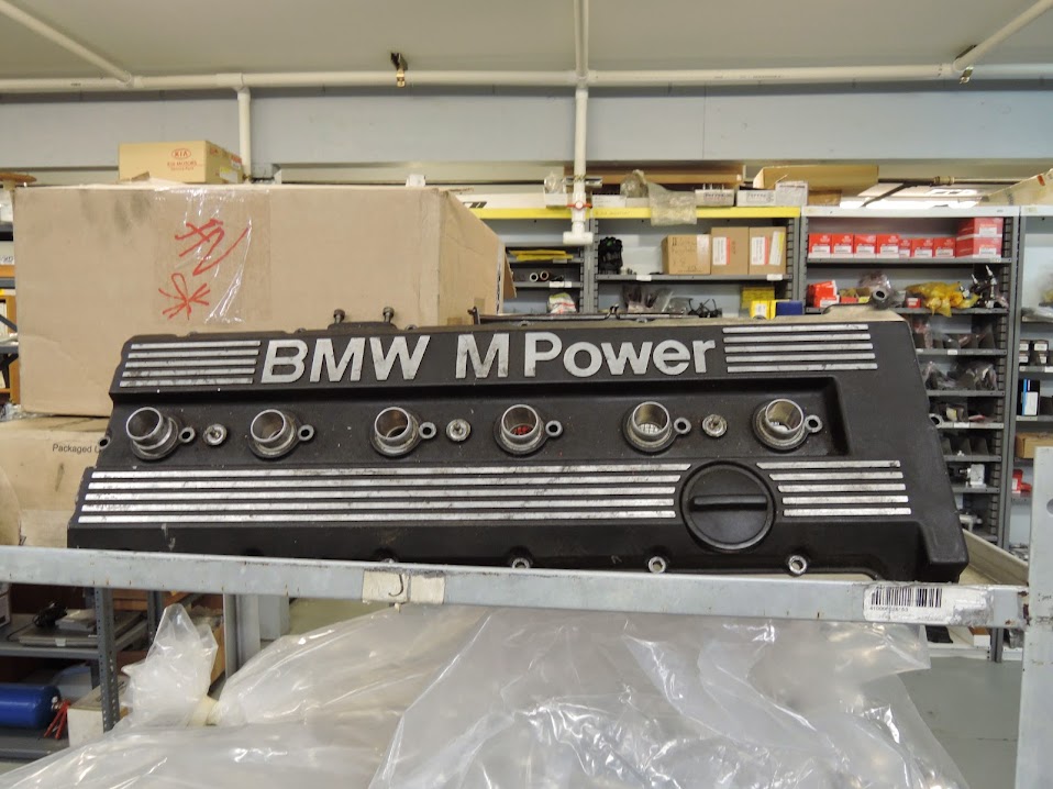
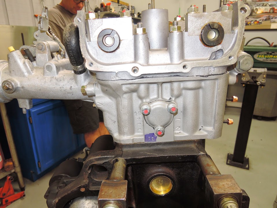
2ed those are the stock s38 b36/38 cam s
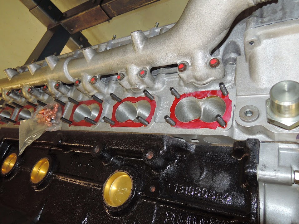
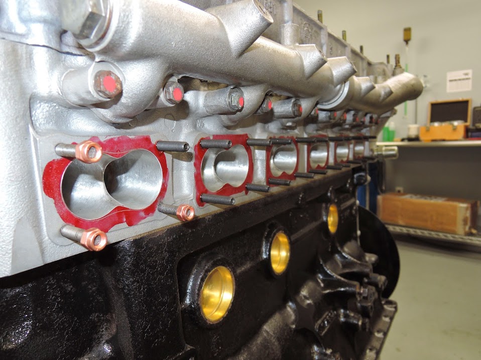
yes the intakes were worked over , I sent the head and intake /throttles to guy with flow bench who did the port work, there was actual science involved, not just "opening up the holes "

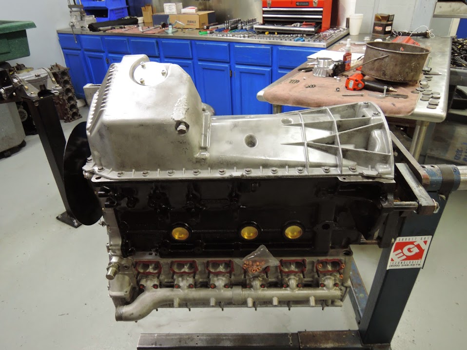
hopefully we will finish getting the cams dialed/degreed in this week

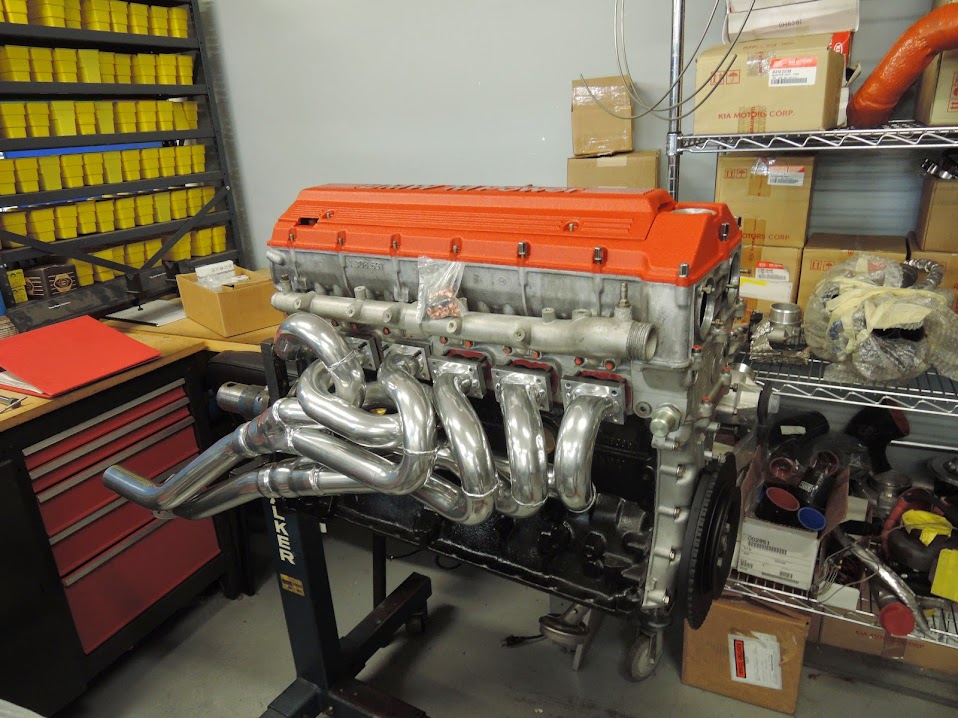
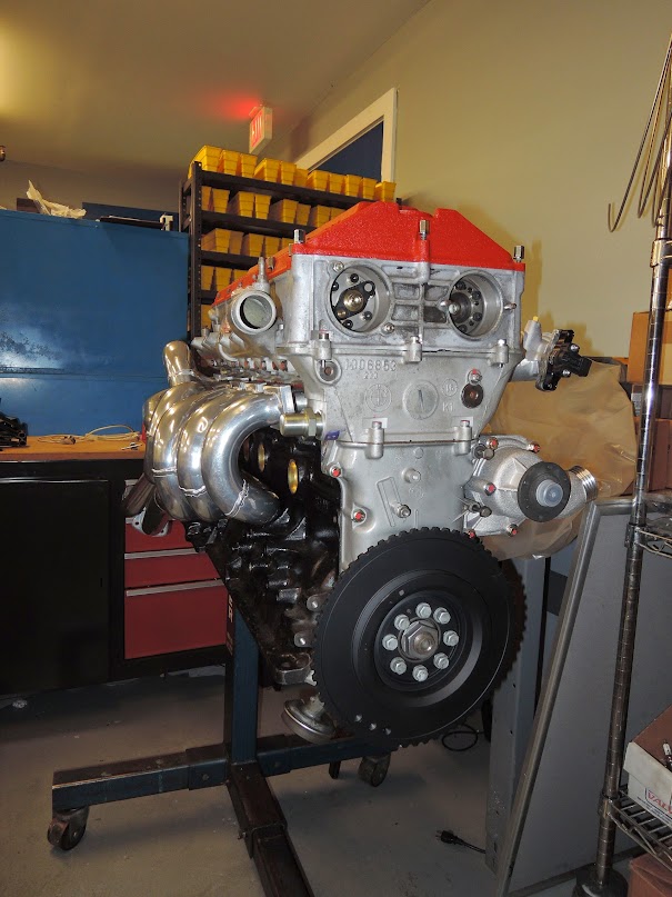
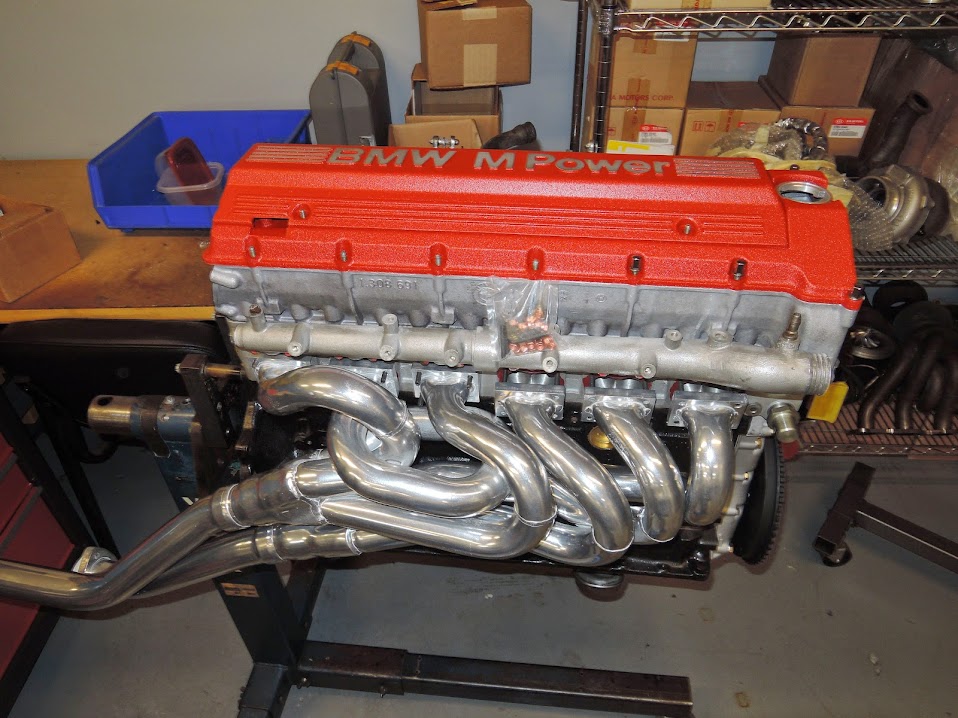
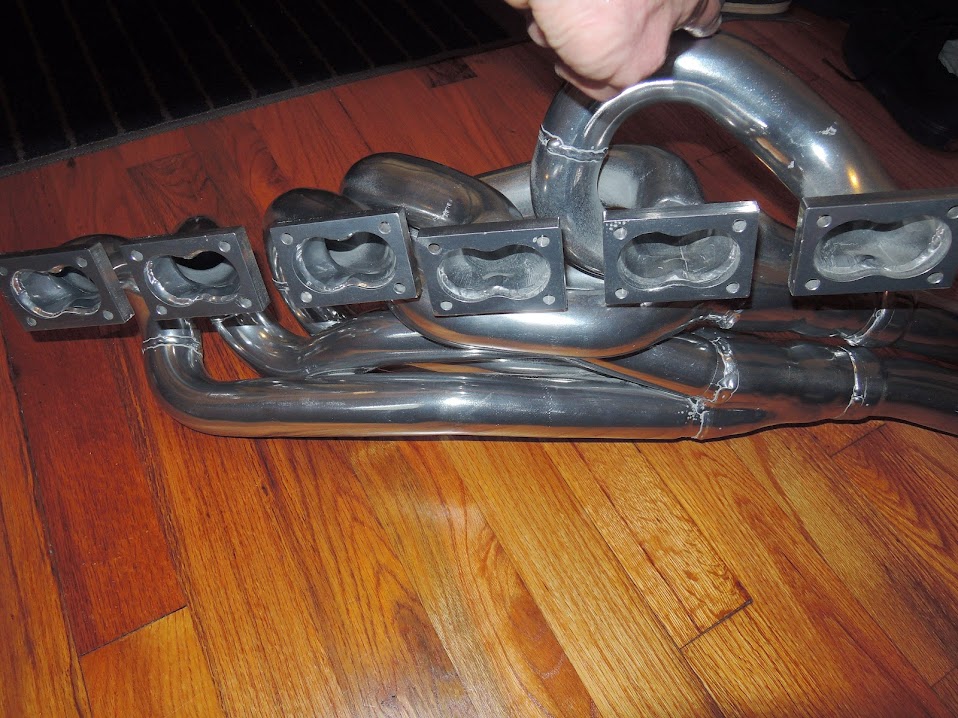
in the meantime some header bling

002.JPG


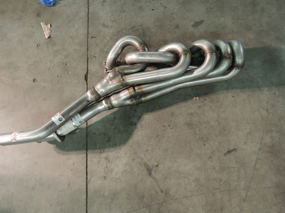
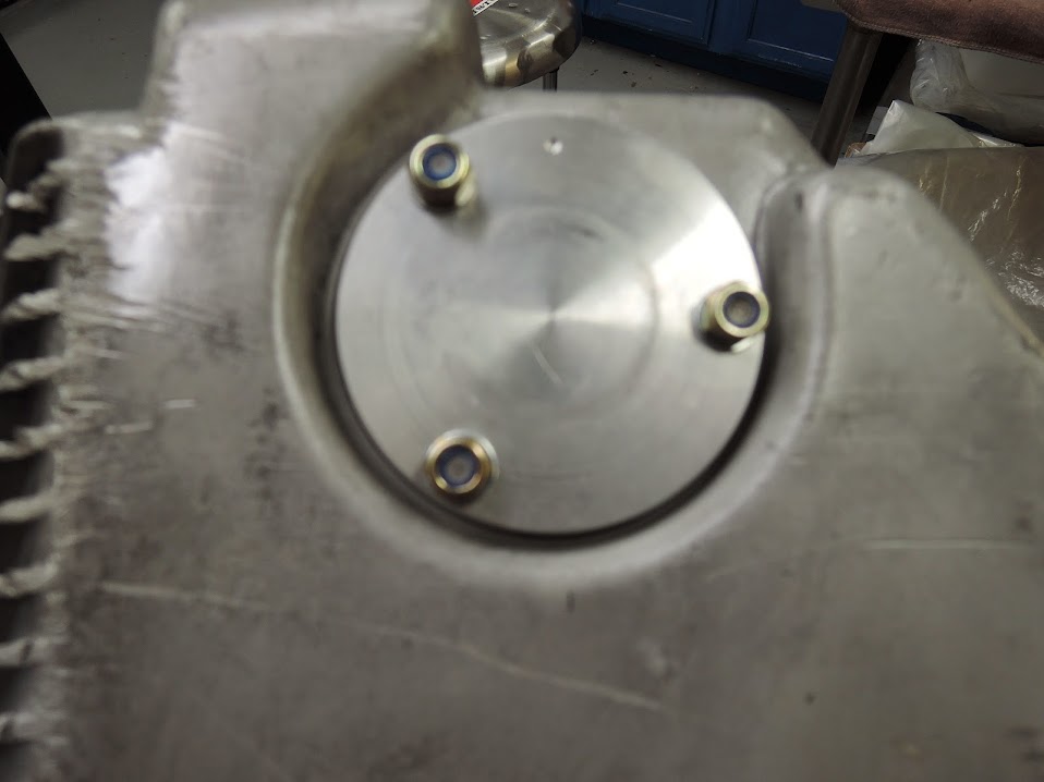
starting with bare euro headers

headers%2B001.JPG


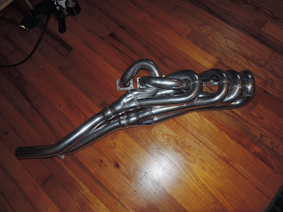
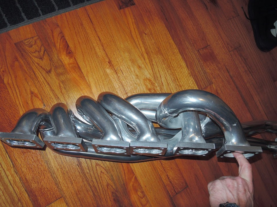
and after the ceramic coating

headers%2B002.JPG


headers%2B003.JPG
 

m5bb

Well-Known Member
Site Donor $
Messages
2,081
Reaction score
909
Location
Peachtree Corners, GA
Thanks B.
Love to know what you set your cams at if you're willing to tell me.
I have adjustable gears for both as well.
Paul was going to help me with the set up but he is really hard to get a hold of.

A good flow guy can do some amazing work. Just never went that far for a street motor.

Bag of snake headers are cool. I just had mine recoated.

Have you decided what management system you are going to use?
Do you know Ed Senf? He tunes the KIA racing team motors and Rum Bum racing Porsche. He is really good on the dyno. Lives in Cumming.

Gary
 

bdigel

Well-Known Member
Messages
534
Reaction score
318
Location
Atlanta
Thanks Guys , stay tuned I hope things keep progressing quickly
Yes I know Ed, and Chris Works with him @ Kinetic Speed shop, , Chris has asked him to do the tune for us when we are ready

in the meantime work on the chassis work has resumed

002.JPG


Frank whittled out this fantastic seat mount , He milled out the bottom and welded in threaded seat stay from the bottom .


001.JPG


that way the seat is adj . for taller Drivers than myself .

003.JPG


view from the top

004.JPG


and how will will fit into the car
 

bdigel

Well-Known Member
Messages
534
Reaction score
318
Location
Atlanta
some more engine bling

cut some holes in the motor mounts to lighten them up

014.JPG


015.JPG


and got my Valve cover and coil cover back from the powder coater

valve%2Bcover%2B002.JPG


those of you familiar with the s38 may realize the different cover, The covers are from the euro s38 b38 with the coil over plug design , which I will be using , to modernize the ing. system . So Im ditching the distributor , the cap, rotor , plug wires etc . along with being a beter system , I think its a much cleaner look

valve%2Bcover%2B001.JPG
 

stphers

Well-Known Member
Messages
1,050
Reaction score
512
Location
Port Moody, BC ( near Vancouver, BC )
engine

Great project, very, very well done. I really like how you are touching everything and upgrading everything.

One question, beautiful job on the valve covers, is that a wrinkle type of fimish? I have been looking for a red wrinkle finish in a powder for a while. To do some of my Alfa and Fiat stuff ala Ferrari testarossa valve cover finish

Kudo's to all your ideas and work

Thanks, Rick
 

bdigel

Well-Known Member
Messages
534
Reaction score
318
Location
Atlanta
Great project, very, very well done. I really like how you are touching everything and upgrading everything.

One question, beautiful job on the valve covers, is that a wrinkle type of fimish? I have been looking for a red wrinkle finish in a powder for a while. To do some of my Alfa and Fiat stuff ala Ferrari testarossa valve cover finish

Kudo's to all your ideas and work

Thanks, Rick

Hi Rick

thanks, glad you like them , I was a bit worried how the wrinkle red would turn out , couldn't be happier, hope it goes well in the car . I had the covers done here locally in Atlanta by smoking gun
http://www.sgpowder.com/

If your going to try it your self I believe Eastman carries wrinkle red powder

Frank and Dave got going on trying to finish up the front end , 1st off is to get the new shocks mounted in the car. they milled out the bump steer spacers from my old car to accomidate the extra length of the shock that protrudes below the spindle

007.JPG


009.JPG


a good close up of the spacer showing the shock cut out , with the shock sitting in it


010.JPG
 

bdigel

Well-Known Member
Messages
534
Reaction score
318
Location
Atlanta
the Brake project is half done, calipers and rotor are mounted . sourced some Porsche Caliper from a 996 and Moosehead engineering made some brackets to mount them to my e28 parts . thanks much to Paul from moosehead

valve%2Bcover%2B003.JPG


valve%2Bcover%2B004.JPG


valve%2Bcover%2B005.JPG


valve%2Bcover%2B006.JPG


to get full pad contact with rotor that fit under 16 inch wheel the caliper mounts got milled a bit

20140512_030114.jpg


the rear mounted , with e34 540 vented rear rotors

002.JPG


003.JPG


front brakes mounted , using my custom rotor based off an 840 csi rotor, Rotor has an aluminum hat to reduce rotating mass

011.JPG


its a tight fit inside the 16 inch wheel !

010.JPG


008.JPG
 

bdigel

Well-Known Member
Messages
534
Reaction score
318
Location
Atlanta
Fabulous project. I've been following your updates with interest. Are the wheel studs you're using standard or extended? I need to install longer wheel studs in order to fit wheel spacers on my car and was wondering what you were using?
Thanks
Niall

Hi Niall , Those are extended studs , and I got them from Bimmer world , they have several types Im sure would fit your needs .

mocked up the valve cover and headers on the engine , should have it complete quite soon , need to finish degreeing the cams in, changing the studs out for the headers , and a few more mods for the coil over plug conversion. in the meantime enjoy the mocked up bling

engine%2Bbling%2B%2Bshots%2B001.JPG


engine%2Bbling%2B%2Bshots%2B003.JPG


engine%2Bbling%2B%2Bshots%2B004.JPG


engine%2Bbling%2B%2Bshots%2B005.JPG
 

bdigel

Well-Known Member
Messages
534
Reaction score
318
Location
Atlanta
Got around to working some more on the suspension . We put the springs / dampners all together , the adj, helper springs , torington bearings to reduce friction etc, etc

001.JPG


002.JPG


some close up's and and installed in the car

004.JPG


and the front assembly put together, of coarse I put it together backwards , , helper spring is suppose to be on top

005.JPG


and put in the car

018.JPG


camber plate

021.JPG
 

bdigel

Well-Known Member
Messages
534
Reaction score
318
Location
Atlanta
so you guys want some more " Engine porn"
Dithered a bit more with the engine the other night
we worked on setting up the Coil over plug, had to reduce the height of the studs from the B36 head to clear the coils .

here is the old valve cover with convential plug wires

008.JPG


which will be discarded along with this distributor piece

009.JPG


and with new coils installed

010.JPG


another shot with the coil cover on , normally on a race motor you would leave this cover off to release heat, but it just looks realy good with it on

012.JPG


also got the oil pan put on

001.JPG


interesting detail is the oil level sensor is removed and replaced with this billet piece to increase the oil volume in the pan ( all though not much )

003.JPG


another minor detail is the water pipe delete block off on the back of the cyl head

005.JPG


new header studs installed

002.JPG


007.JPG
 

bdigel

Well-Known Member
Messages
534
Reaction score
318
Location
Atlanta
After 18 months we got the car back on the ground rolling and steering ! Big day ! still have to finish up the detail on the front suspension but it hold's the car off the ground and the steering works .

one thing that had to be done was the steering knuckle/ lever had to be modified to work with the rack and modified to correct the geometry , etc.

005.JPG


017.JPG


XHuyjbXED-C6aB9wV9Vw5rVhqwLjVTkPZZ7DX6Vc40o=w274-h204-p-no


the finished knuckles below

Ug6tT5M_eoz5gQT8mv0bhrCuZzlwYBghZ0IJGXHgMhc=w257-h191-p-no


007.JPG


and installed with the rest of the suspension

018.JPG


the next big step is the new steering shaft . we cut out the old stock stuff and with the rack conversion , needed an entire custom deal.
below we are staring to mock up the shaft placement , for length , where it will go though the firewall, and the bearing mount placements

013.JPG


close up of the steering shaft firewall mount bearing , also notice the new throttle pedal set up

008.JPG


extra long shaft waiting to be cut to size

009.JPG


view of the steering shaft from the engine bay, , notice the firewall bearing and the two new universals. mounted into the rack with out the flex coupler

013.JPG


close up from the firewall

014.JPG


and into the rack

017.JPG


close up of the steering wheel, hub, and quick release mount

011.JPG


010.JPG


037.JPG


shaft cut down to size,

036.JPG


038.JPG


****pit coming together

039.JPG
 

bdigel

Well-Known Member
Messages
534
Reaction score
318
Location
Atlanta
the first time we sat the car back on the ground , we had one minor problem ( or major) with the wider tires and wheel , and trying to lower it, the fenders sat right on to the tires , not allowing the car to roll or be lowered where it needs to be . since Im install fender flares , its time to cut . , So Frank an I cut both the outer and inner fenders , stretched the inner fender and shaped it to clear the tire's , and tack welded them back together for strength

first time back on the ground but sitting on the tires

023.JPG


022.JPG


fender before the modification's

Ma2S9DMFtpkSsa21Nmj06GuRPf7GHkmeKNH3nCNDzBE=w264-h198-p-no


drawn out line for cutting

022.JPG


outer fender cut out

2QW-Wo1JVJrRcWv7AwkjFSmWq8gffMDDBguQreF_vHI=w307-h230-p-no


bending /stretching, shaping the inner fender

1kuvciLuMZvyeRGus0BmI4JwMkI7fBK9uRUlUmk0Xic=w307-h230-p-no


n4fGQ3MNpgTpBmIlXVp9jFu3NR1U69iFHM9WbD38PhA=w173-h230-p-no


inner and outer fenders tack welded back together

on48cWMb6gCao8P-vDB-SuXiDr4N960RhgZ6G2qn7pw=w307-h230-p-no


close up

027.JPG


front before cutting up

028.JPG


and slammed on the ground

029.JPG


close up of the rear

030.JPG


quick mock up with the fender flares , note these are not the wheels the car will be run with

032.JPG


033.JPG


It was a lot of work to get this far, converting /rebuilding front and rear suspension's, fixing the geometry for the lowered race purpose, converting to the steering box, raising the floor to get the exhaust of the ground, and cutting up the fenders, definitely not the short cut the stance kids take !! a functioning lowered car , I f you look at pictures of typical Race CSL's they ride quite high . We spent a lot of time and effort to get this thing lower, hopefully it will pay off in handling

one more time cause I like this shot

034.JPG
 

Gazz

Well-Known Member
Site Donor
Messages
945
Reaction score
620
Location
Gold Coast Australia
Fantastic stuff Brendan. I'm following this closely as I'm doing almost the same steering conversion on my coupe using a power assisted E21 steering rack instead of the manual rack you have installed.
In my case it's just as much for the RHD header clearance for the S38B36 installation as it is for the better feel and simplicity of a rack.

I'm not going to make up a new A arm mount as you have done in order to retain as much of the original travel geometry and turning circle as possible.

In the pics shown I need to have the red and green lines the same length, correct? In the second pic I have set up the E9 female threaded adjuster and E9 tie rod end to work out how much extension to add to the rack tie rod via a sleeve and threaded rod.

The blue lines need to be the same length, which is the centres from the E21 knuckle on the base of the E21 strut, correct? I measured this as 125 mm ball joint centre to ball joint centre vs 217 mm on the E9 knuckle.

What was the welding method you used when shortening the one piece forged E9 knuckle. This is not something I want to fail.

Many thanks if you, or anyone else, can spare the time to answer these questions. Gary
 

Attachments

  • Steering rack 1.jpg
    Steering rack 1.jpg
    94.2 KB · Views: 288
  • Steering rack 2.jpg
    Steering rack 2.jpg
    94.1 KB · Views: 304
  • Steering rack 3.jpg
    Steering rack 3.jpg
    97.3 KB · Views: 277
Last edited:

Gazz

Well-Known Member
Site Donor
Messages
945
Reaction score
620
Location
Gold Coast Australia
Don't worry Brendan, the amazing Paul Cain has answered my queries. I will however be buying the brackets from David at Synchro.
 

bdigel

Well-Known Member
Messages
534
Reaction score
318
Location
Atlanta
one last piece of Chassis work , as noted we boxed in the front frame rails with the firewall to give the front end more strength .

012.JPG


013.JPG


and welded into place

015.JPG
 

Nicad

Well-Known Member
Site Donor
Messages
3,503
Reaction score
536
Location
Toronto
You really get a feeling for how many separate decisions must be made and thought out when custom fabricating a vintage race car.
 
Top