Blue EV build

Nothing amazing to report but small progress here and there...

We installed locks in the battery box to secure each battery. These are hex bolts that clamp against notches in the battery rails. They push the battery against one side, locking them laterally and the bolt fits into a notch that locks them longitudinally. The locks are really nothing more than a square nut welded to the rails but it will be very secure.

batteryboxclamps2.jpeg


We installed the steering column to assure that the coupling joint at the steering gear box clears the battery box and it does. Not by a lot but by enough.

20200724_162819.jpg


20200724_162215.jpg


We got the Franken half shafts from the Driveshaft Shop and they look great but when we went to install them we noticed that the axle seals on the Tesla motor/diff were damaged so we're awaiting new seals before installing the axles.

20200724_163439.jpg


20200724_164325.jpg


The next problem to solve is the brakes. The original booster mount had to be lopped off the pedal box to make room for the batteries. The plan is a remote master/hydroboost installation using a small "master" cylinder on the firewall/pedal box mounted where the clutch master would normally be. That will be actuated by a rod attached to a lever welded to the single brake pedal pivot. That "master" will send hydraulic pressure to a slave cylinder on the back of a hydroboost system that then pushes a boosted rod into a real master that actually sends pressure to the brakes. There should be room between the battery box and the inner fender for the remote unit. This will require adapting a Wilwood master to the dual line front ATE calipers and a few other small issues yet to solve.

20200724_162944.jpg


wilwood single master.jpeg


hydroboost.jpeg
 
Wonderful build thread. As a relative new owner of a coupe and having driven a 90S Tesla for 6 months, the CSE has to be one cool car.
 
Hard to believe that it's been so long since last post that this thread was pushed down to the 8th page. We've been focused on refining Paul's car so mine hasn't been getting much love but things are starting to gain momentum.

As you've no doubt read, Paul has been driving his CSE and recently installed the Orion Battery Management System. That led to a lot of opportunities for software enhancements on the dash app.

Prior to the BMS, we were estimating range based on instantaneous voltage from the Tesla Drive Unit Controller. This was less than ideal because instant voltage varies a lot with load and we had to guess at min and max voltages in order to calculate range. I evened out the variances by using an average over 1,000 readings (10 seconds, as the messages come in on the CAN bus at 100Hz) and it worked but wasn't perfect. Additionally, we were flying blind with regard to battery temperatures and had no insight into what was going on when charging. The BMS offered the opportunity to address all that. It allowed us to wire up the thermistors in each battery cell and has configurable CAN bus messages that it sends with a variety of battery information that we are able to use for better display of battery state, health, range, etc.

Here's a small sampling of the information we can now use and display from the BMS:

Pack State of Charge (SOC), Pack Adaptive SOC, Pack Health, Pack Amp Hours, Pack Adaptive Amp Hours, Pack Voltage, Pack Current, Discharge Current Limit, Charge Current Limit, Discharge relay state, Charge relay state, Charger safety state, Malfunction indication, Multi-Purpose Input signal status, Always-on signal status, Is-Ready signal status, Is-Charging signal status, J1772 Plug State (Plug is disconnected, Plug is inserted but the button is depressed, Plug is inserted and button is not pressed - BMS is preparing to allow charge, Plug is inserted and the BMS has activated the J1772 compatible charging station), DTC statuses (Discharge Limit Enforcement Fault, Charger Safety Relay Fault, Internal Hardware Fault, Internal Heatsink Thermistor Fault, Internal Software Fault, Highest Cell Voltage Too High Fault, Lowest Cell Voltage Too Low Fault, Pack Too Hot Fault, Internal Communication Fault, Cell Balancing Stuck Off Fault, Weak Cell Fault, Low Cell Voltage Fault, Open Wiring Fault, Current Sensor Fault, Highest Cell Voltage Over 5V Fault, Cell ASIC Fault, Weak Pack Fault, Fan Monitor Fault, Thermistor Fault, External Communication Fault, Redundant Power Supply Fault, High Voltage Isolation Fault, Input Power Supply Fault, Charge Limit Enforcement Fault), Highest Cell Temperature and Cell ID, Lowest Cell Temperature and ID, Average Cell Temp, Internal BMS Temp, Fan Speed, High and Low Cell Voltages with IDs, High and Low Cell Open Voltages with IDs, High and Low Cell Internal Resistances with IDs, Average Cell Voltage, Average Cell Open Voltage, Average Cell Resistance, Number of cells, Battery Cell Broadcast (per cell id, instant voltage, resistance, open voltage)

Whew! Those are just the values we are currently reading and integrating into the dash. There are actually lots of others: https://www.orionbms.com/manuals/utility_o2/ As you can imagine, the challenge is how to display all that in a logical, meaningful way, using primarily just the hole where the tach used to reside. In general, I tend toward displaying too much information and Paul leans towards consumer-like simple interfaces. The division of labor is: Paul does a design and I do the coding. Together, we're honing in on what I think is a really nice app.

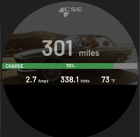
We added a couple new pages to the app and some new "idiot light" icons to the main page. (Pages are accessed via button on the steering wheel stalk on Paul's modern steering column -- I haven't yet determined how I'm going to implement page toggling in my car). There is a new "charging" page that automatically pops up whenever we detect that the car is charging. This shows the current charging progress, volts, amps, most relevant (closest to max) temp, any malfunction information, etc. This page is not in the page "rotation" if not charging. There are, however, two new diagnostic pages in rotation, one for the BMS, and another for the batteries. These complement existing diagnostic pages already in rotation for Tesla-related information from the Drive Unit Controller. However, we found that it was annoying to have to cycle through too many pages while driving so we added a little logic so that if aren't toggling quickly we bypass all the "diagnostic" pages and just flip between the digital and analog speedo pages.

There are also new pages in the touch screen version of the app that Paul isn't currently using but I plan to locate behind the speaker grill in the dash in my car. This screen allows changes beyond just what we can accomplish with a couple buttons (page toggling and sport mode via shifter).

If you haven't seen the app in action you can watch an early version in Paul's car here:

The page that displays while charging...
Charging.png

In case of a malfunction while charging....
ChargingFault.png


We searched long and hard for a font that is close to the original VDO font...
AnalogFont.jpg


All the potential "idiot lights" (creep mode, traction control, cruise control, limp mode, instantaneous voltage dropping below min, CAN bus disconnected). The vertical gauge bars for range and temp also change color to orange, then red as they approach limits.
LimpMode.png
Icons.png


Sample diagnostic pages:
BMSDiag.png
BatteryDiag.png
Temps.png

Or, via touch screen:
Screen Shot 2020-12-23 at 11.00.44 AM.png
 

Attachments

  • Charging.png
    Charging.png
    1.1 MB · Views: 198
Despite the fact I'm real purist, wanting to keep E9 in original (or only slightly modified) condition I'm really for your project. You are doing fantastic project!

I could even imagine someone (you?) could make short series of of E9s-look EV, built on a light frame with Tesla powertrain and E9 shell on it.
Depending on verions it could still be original E9 interiror or really custom.

Sounds like a business case?

Amazing job. You've blowed my mind! Happy New Year ... Let is bring you joy and even more fun in 2021!
 
Transitioning from all software to mostly hardware... Recall, instead of a dial or buttons to select gears, I am using the original automatic shifter. Trouble is, the detents were in the trans and I need to translate the linear movement of the shifter into a 12v signal for each gear. Truth is, the Tesla only has R/N/D but I'm using Park to activate the electronic parking brake (more on that in another post) and Low to select "sport" mode that ups the output discharge current limit from the normal 80% to the full 100%.

Regardless, I needed to create something to provide positive, electronic gear selection so I got into CAD and 3D printed a unit that uses 5 microswitches with a sliding plate. I remade some of the parts in aluminum for thread strength and reduced size and put it all together into a "sealed" black box. It isn't waterproof but is water and dust resistant. Combined with some throttle linkage, we fabricated a mounting bracket, welded in a couple studs, and mounted it to the car. It works perfectly.

Next time, brakes...

shifterParts.jpg


blackBox.jpg


shifterTest.jpg


shifter.jpg
 
An interim post as we work some things out. Bolting in an electric motor and some batteries is the easy part. The devil is in all the little details and decisions that need to be made to retrofit and replace needed systems like braking, power steering, cooling, HVAC, etc. I realize none of this has any bearing on normal e9 ownership but some have expressed interest and eventually I'll get to restoration topics and need everyone's help....

The biggest hurdle yet to overcome is braking. Paul changed to Wilwood all around and devised a very clever mechanical solution (Fred) to change the direction of brake pedal travel and translate it into the transmission tunnel area where he mounted a hydroboost and Wilwood master in a backwards orientation. All that scared me and I had already rebuilt the stock ATE brakes before deciding to go EV so I had hopes of retaining stock braking all around.

But hopes are often crushed and there just isn't room in the engine bay for 10 Tesla Model S batteries and a brake booster/master. I contemplated manual brakes, given all the regen braking I get for free, but sure footed stopping power is too important so I had to figure out a way to get power braking into the car somehow. With some help from Matt at https://www.powerbrakeservice.net/ we devised a system that has a simple single reservoir master on the firewall, activated by the brake pedal that then pushes fluid to a slave cylinder that then pushes on the Bosch hydroboost unit, as if it were actually the brake pedal rod, which then pushes on the master cylinder. Ir order to get the piston sizing all correct I had to ditch the stock master in favor of a Wilwood dual unit. It only has 4 output ports, instead of the ATE's 5 so I'll need to Tee the front lines to the dual hoses on the front calipers.

But before I can even get that far some work needed to happen in the pedal area. The battery box encroaches on the area where the brake pedal rod normally exits the firewall but the area for the clutch cylinder is open so we had to mount the new "master" there. Of course, we don't want to use the clutch pedal to slow the car (this isn't a Model T after all) so we sourced a pedal from an e28 and did some machining and welding to fuse the two pedals together. But it turns out that the e28 clutch pedal is about 1/2" farther to the left so we had to move it in a bit to align with the hole in the firewall. This was all a lot of work. The inner pivot had a spacer welded in the middle between the two pedals that had to be machined off in the lathe and then the e38 pivot tube is longer than necessary so that had to be milled down to the precise length so that it is about 1mm than the inner pivot so that, when bolted to the car, the inner pivot is held tight but the pedals are free to swing without any side to side movement. When all done it works and looks fine (obviously it all needs to be cleaned up) but the pivot tube was about 1mm out of true, making it hard to fit the '73 style long bushings in. I actually only had the one long bushing from the brake pedal so I had 3D printed a second one (in orange) as a stand-in until I could source an original Nylon bush but since they didn't fit perfectly I was forced to opt for Plan B. The e28 pedal came with the smaller split plastic bushings that just fit on the ends. These are more what I'm used to in the old Chevrolets etc. and they fit and work perfectly (once we milled another mm or so from the pedal pivot length) so that's what I'm going with.

When I say firewall I really mean the steering column bracket that is bolted to the firewall and dash. We had already lopped off the stock brake booster support tube and destroyed the nice new powder coating so we needed to blast off the coating and seal up the big hole that was no longer necessary since we won't be running brake or throttle linkage through there. Of course, we're weren't lucky enough to have the ears on the new master exactly match the pattern of the stock clutch master so we had to gusset and weld that up to make it strong with the correct bolt pattern. We welded studs to the bracket so that R&Ring the master doesn't require crawling under the dash to keep the bolts from spinning. Once done, we have a brake pedal operating a small master. I minor accomplishment but we didn't realize that the mounting surface for the clutch master isn't perpendicular to the ground (the stock clutch cylinder must have an angle to the ears) so the new master is tilting down slightly. I don't think this would have any material effect on the operation, other than preventing full fluid level, but it bothers me enough that I think we'll have to address it.

The next step for braking is to mount the slave/hydroboost/master combo in the transmission tunnel area but we also need to fit the hydraulic pump into that area so I sourced an electric power steering pump from an 02-06 BMW/Mini and we are currently working out how to fit both pieces into the tunnel area, while still leaving room to get to hose fittings, and most difficultly, how to route the hoses/lines from the reservoirs down to the master/pump.

The final two parts of the brake system will be the lines and the parking brake. More on those later.

In the meantime, there is one more pedal to setup. The throttle pedal is an electronic potentiometer and there wasn't enough room between the steering column bracket and the trans tunnel hump to fit it properly. I always look to Paul's solutions first. He cut into the tunnel to make more room but I didn't think that was necessary so instead, we opted to relieve the steering column bracket a bit and bend it inwards to make room for the pedal assembly. We still need to fabricate a mount but we have the room for it now.

blasted.jpg
masterMounted.jpg
masterMounted2.jpg
pedals.jpg
throttlePedal.jpg
masterFitment.jpg
masterStuds.jpg
masterHolePattern.jpg
masterAlignment.jpg
columnFill.jpg
pedalRelocation.jpg
throttlePedalTooLow.jpg
brakePedal.jpg
psBrakePump.jpg
 
Again no normal e9 applicable content so skip if a purist...

Brakes Plan B.

After doing all the work to adapt the small master cylinder to the clutch side of the brake pedal I learned of an alternative approach that was promising. Tesla uses an electric brake booster from Bosch called an iBooster. It has a pedal sensor built in and sophisticated electronics to allow braking by wire over CAN for Auto Pilot but some people smarter than me figured out you can run it in"failsafe" mode with just a 12v input and you get power brakes without vacuum or hydraulics. Best of all, it's a fairly compact unit and there was a chance it could squeeze in between my battery box and the inner fender, in roughly the normal location for a mast cylinder, thus obviating the need for any remote placement shenanigans.

20210312_140129.jpg


20210312_135537.jpg


So I bought an iBooster from a wrecked Tesla and did a test fit. It's tight but it will work. Now I just need to modify the steering column bracket once again to mount it and run a rod through the mount to the pedal. Should be no problem.

While discussing brakes... The Tesla drive unit only has Forward, Reverse and Neutral. There is no Parking pawl. On a real Tesla there are electric worm-drive parking brake calipers that clamp down on the rear discs when park is engaged and stay there even when power is cut. Paul adapted those to his car because he was already fabricating new caliper mounts for his Wilwood upgrade but I'm sticking with stock brakes so that wasn't an option for me. Initially I thought I'd just flash a "Pull Hand Brake" type message on the dash app when you engaged Park but I found a better solution with a product called eStopp.

20210215_162245.jpg


parkingBrakeFill.jpg


20210312_132246.jpg


20210312_132540.jpg


It is a linear actuator and control module that pulls to 600 pounds and then stops. Being a worm-driven linear actuator, it stays in place when power is cut. It is designed for hot rods, etc and comes with a push button for operation but it was a simple task to adapt the electronics to my new shifter mechanism. Fitting it to the car took a bit of planning since I didn't want the parking brake cables to hang below the rear suspension crossmember. In the end, I opted to drill two holes through the lower portion of the crossmember for the cables and fabricated a bracket that attached to the previously fabricated brace in the trans tunnel. I removed the parking brake tubes and handbrake mount and filled in the hole in the tunnel, cut the cables, swedged on a couple cable ends, and now the car won't roll when it is put into park. Check it out below (ignore the banging -- that's elsewhere in the shop):


Tyler began building aluminum skins for the front battery box and built the racks to mount 4 Tesla battery modules in the rear. I ordered an onboard charger and DC/DC converter as well as the BMS. Soon I'll be installing the batteries and wiring it all up.

batteryBoxSides2.jpg


batteryBoxSides.jpg


20210402_140146.jpg


messages_0 (2).jpeg


Tyler also smoothed out some previous crash damage in the right front that hadn't been metal finished to our standards and he has begun fitment of the rocker panel covers, which I also sandblasted and plan to paint body color so they need to fit perfect.

20210215_132554.jpg


rfDentRepair.jpg


Oh, and Tyler began work on building my custom front bumper. I am using a 2000 CS all-chrome rear bumper and I want a front bumper to match -- no rubber and no overriders. We sandblasted the chrome off and he patched in the holes for the rubber strips. Now he is going to wed the three pieces together into a single seamless bumper without visible hardware or overriders.

20210402_140215.jpg


messages_0 (4).jpeg


frontValenceRepair.jpg


messages_0 (5).jpeg


messages_0 (3).jpeg
 
I promised I'd share the missteps as well as the successes....

Where were all you eagle-eyed lurkers last May when I shared photos of the rear suspension install and "3rd member brace"? Notice anything odd now?

I happened to see a photo of the underside of someone's car and realized that the rear anti-roll bar ends up located directly in front of the rear crossmember -- right where I had run my parking brake cables. So I pulled my swaybar out of storage and went to see if it was going to interfere. But where does it mount? Argh! With the diff bracket cut off it becomes possible to forget the proper orientation of the crossmember, and with a 50/50 chance of getting it right, wouldn't you know -- I installed it upside down. I count on you critics to point out stupid stuff like that -- why'd you let me down? :oops:

e9RearSuspensionUpsideDown.png


Surprisingly, the trailing arms fit, and it all pretty much works that way. Except for the swaybar. And maybe some important geometry. Of course, I'd never leave it like that so it all had to come apart and I'll need to re-fabricate the center brace and parking brake cable setup. That's why a love welding over woodwork -- so much easier to fix your mistakes.

In the meantime, I've made lots of progress on the brake booster, BMS, wiring, etc. but I'll share that later.
 
Thanks.

Paul and I will be in La Jolla with the CSE this Saturday for those of you in So Cal who want to see an EV coupe.

In the meantime, here's an update on my car...

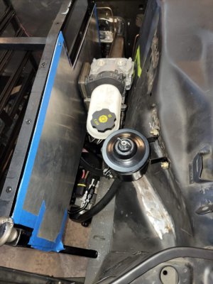
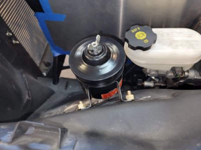
As mentioned previously, I decided against the remote hydraulic brake boost solution in favor of the Tesla/Bosch electric iBooster mounted in more-or-less a normal location ahead of the pedals. The battery box dictates sliding it all over to the left, using the clutch hole instead of the normal brake hole. I purchased a precut flange from Lars at evcreate and Brett came up with an ingenious solution for adapting the large hole in the booster to the small clutch linkage hole in the steering column bracket. He rolled some sheet metal into a cone and tightened it up by pounding it into a piece of pipe. Some nice TIG welding later and I had a Dr. Suess Poogle horn that very securely mounts the iBooster/master. We added a bracket for a Wilwood proportioning valve and some gussets just to make absolutely certain it will not fatigue over time and then literally jumped up and down on it to test strength. No finite element analysis for us. I still need to finish connecting the master to the pedals and then fabricate all the lines.

A tight fit
iBooserTIGFlange.jpg
PoogleHornInstalled.jpg
PoogleHorn.jpg
PoogleHornTesting.jpg
iBoosterLinkage.jpg
iBoosterInstallation.jpg
iBoosterMounted.jpg


Work then turned to the battery box again. I have the Orion BMS 2 and thermistor expansion module for managing battery charge/discharge as well as health, state of charge, and temperatures. Aftermarket battery management systems can't use the proprietary Tesla circuit boards on each battery so I replaced them with some simple cell tap boards from 057 Tech that allow me to connect the 6 cell taps and 2 thermistors per battery to the BMS via standard JST-XH "molex" plugs. I was pleased to learn that my wife's p-Touch label printer works with Brother HSe heat shrink tape. Super clean.

Before attaching the connectors to the harnesses I need to accurately measure the length for each battery module, which means committing to a location for the BMS. Ideally it would live inside the battery box and I happen to have a decent sized void where the box jogs around the steering box so we made a shelf to mount it and cleaned up the welds on the box in general. The BMS fits in with plenty of room to spare.

CellTapBoardInstallation.jpg
CellTapBoards.jpg
BatteryConnectors.jpg

BMSShelfFab.jpg
BMSShelf.jpg


CoolantManifolds.jpg
TeslaBatteryCoolingSimple.png


I also planned the cooling lines for the batteries. Ideally they'd all be fed equal temperature coolant in parallel and I contemplated using a 10-port manifold but the irregular alignment of my batteries makes for a lot of connections so I've decided to run the coolant into the batteries in sets of 4 (and one pair) instead. This allows use of a simple 3-port manifold for the front 10 batteries and no manifold at all in the rear. I got a complete set of the OEM Tesla snap on coolant line connectors for connecting to the batteries and a variety of barbed fittings for the other ends. I have a Bosch electric water pump, a new AC condensor, a new SPAL 16" fan, and a 16" square radiator with threaded bungs for inlet and outlet. Still need to fabricate mounts, get an overflow tank, a lot of heater hose, etc.

I also got an Amphenol UPC high voltage plug (socket is on back order) to install into the box to make it safe and easy to connect/disconnect. The assembly instructions are 12 pages long. Hopefully the next update will have the battery box all wired up and complete.
 
My inner nerd far overpowers my inner purist. This is such an amazing build to follow. Cannot wait to see what's in store next!
 
Does anyone else watch those car build shows were they have these awesome builds with ton of money, and I sit there thinking it's another world. I can't relate to hardly anything they do because it's so way beyond me. Following this thread is the same way. LOL
 
That was @JetDexter 's car -- mine is still in progress, but yes, I drove it down with Paul. His build thread is here. We had a great day, the car was flawless to drive, and there were a lot of great people there to meet. Thank you again Carl! Honestly, I don't care about anyone else's opinion on electrification. SuperfastMatt pretty much sums up my feelings on the whole "you're ruining the car" thing...


My USA-spec automatic transmission coupe was never going to live on forever as a stock example of the venerated BMW E9 coupe. Personally, I wouldn't modify a CSL if I were lucky enough to own one. But I'm not. Everyone should do to their car what makes them happy.

Not to be a dick, but I've never been on facebook and don't intend to start now. I'm not sure what you mean by "ask you anything". I share on this forum because there are smart people who know a lot about coupes. I am interested in what members here have to say, because it is usually constructive in some way. I'll leave facebook to others, thanks.
 
Too busy for detailed updates but a few pictures just to keep the thread up to date...
20210703_161253.jpg

New rear suspension "bridge" to triangulate the rear cross member to the chassis without the stock diff. Has parking brake cable tubes integrated for electric brake actuator. This version bolts to rear cross member for easier servicing. Other end is located via Chevy Suburban motor mount bolted to driveshaft tunnel/floor.

20210703_161348.jpg

Rear crossmember with bolts to bridge and holes for parking brake tubes. Note to anyone else doing this (as if): the stock diff is not centered on the crossmember.

20210710_115701.jpg

Bridge in place with parking brake system safely tucked up high.

20210724_145002.jpg

Now the rear anti-roll bar fits. And brake cables are tucked up nice and high.

20210717_161835.jpg

Brake pedal finished. Not super pretty (I had a few iterations of this as I changed from hydroboost to Tesla iBooster) but it works perfectly and is strong. Used stock rod and clevis as the other end threads just happened to match the iBooster).

20210709_213546.jpg

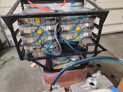
Cooling tubes for front 10 batteries routed. 3-port manifolds not yet secured.

20210719_105916.jpg

Busbars all connected. Batteries only partially charged (21 volts each vs 28) but still enough to hurt you. Will be plating and orange vinyl coating the custom busbars later.

20210719_105933.jpg


20210724_144251.jpg

Large parallel flow AC condenser and Spal pusher fan. Fan not secured yet in this photo.

20210724_144928.jpg

Mini Cooper electric hydro pump for power steering mounted. Two shifter kart radiators mostly mounted (final tabs not finished in this photo). I used two radiators more for packaging than anything else. The upside is that I can run separate cooling loops for the batteries and the Tesla drive unit/on-board charger/DC-DC (all of which runs hotter than the batteries). The downside is needing two water pumps.

20210724_161509.jpg

(Just) Enough room between radiators and battery box to connect hoses.
 
The fan will be the only noisy thing. I need the clearance. We'll see.

Too busy to write up big updates and, since 95% is not relevant to the rest of you, I'm not sure how much anyone really cares but I'll keep the thread somewhat up to date...

The plan is to drive the car under its own power (in the parking lot without glass) by end of month. If I don't post again by then please poke me.

Since last post:
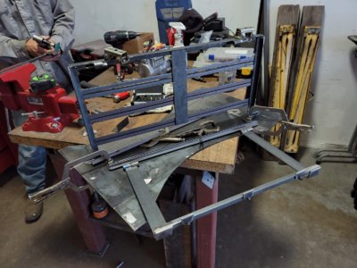
  • Finished rear battery racks
  • Cooling system bench and pressure test (flow fail)
  • Fabricated power steering hoses, A/C hoses, and brake lines
  • Front battery box skinned with extension box
  • All BMS and high voltage wiring at batteries finished
  • Mounted Tesla electric A/C Compressor
  • Digital to analog fuel and temp gauges (via stepper motors)
Failures (since I like to highlight them) include:

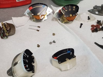
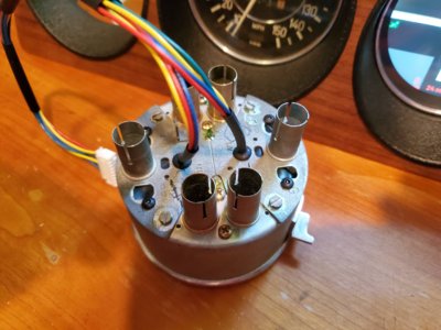
I gave up trying to digitally simulate the fuel and temp sending units to drive the original gauges for range and most relevant temp. After many failed circuits that did manage to move the needles but were too sensitive to changes in voltage and resistance in the system (such as turning on the dash lights), I capitulated and replaced the gauge guts with stepper motors. These are easy to control. The hard part is attaching the needles to the slightly larger spindles -- I haven't done that yet.

The battery coolant test was a success in that there were no leaks but a failure wrt flow. Coolant just barely trickles through the circuitous path of ribbon cable winding between all the cells. My original plan of running 4 sets of 4 batteries in a combination of parallel and series will not work. There is not enough flow from one battery to get through the next three. I will be changing to a fully parallel setup. The slow flow isn't a huge issue, as I have separate cooling systems for the batteries and the drive unit and onboard charger/dc-dc converter, which need more flow. Paul ran for a year with no battery cooling at all -- we don't heat them up with fast charging or desert race track driving so any flow at all is fine, mostly just to evenly distribute and measure the heat.

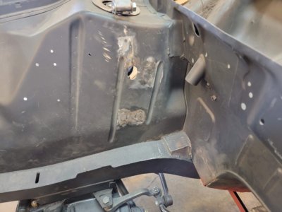
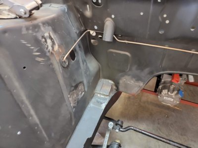
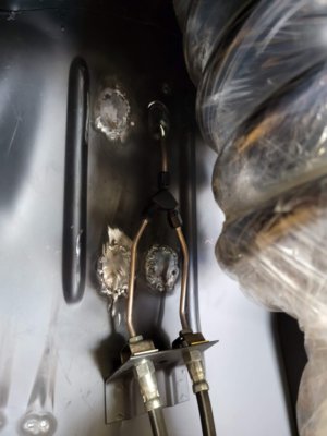
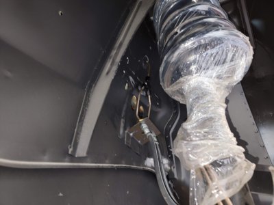
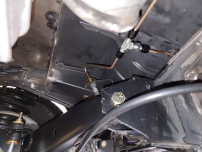
Fitting the front brake lines had some failures, mostly due to the dual circuit nature of the stock ATE front calipers. The Tesla iBooster only has two outputs: one for front, one for rear. Oh, and they are a crazy mix of 12mm threads but ISO double flares. Those feed the Wilwood prop valve, which has three outputs (2 front, 1 rear) but that meant still needing to split the fronts. The other issue was a lack of space on the right side between the battery box and the fender apron. There just wasn't enough room to run a line down there so I welded the two oval holes in and cut new ones up higher, where the apron flares out giving more room. However, I had already cut two holes when I realized I only needed one since the higher location allowed for the Y-split to live in the wheel well instead of the engine (battery?) compartment so I had to fill in one of my holes. For symmetry and to allow room for the outboard Y on the left side, I raised the hole for that one too. Fortunately I had learned my lesson by then and only cut one hole. At least the brake lines are all done now.

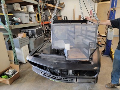
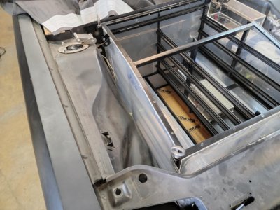
Fitting the front battery box after it was skinned in clear acrylic pointed out a couple areas so tight that that 1/8" caused interference. A little trimming of the skins and some metal massaging were required to get the box to fit perfectly again. I also forgot that I had the lower skin in space when I did some welding and burnt a couple pock marks into the bottom of the box. These will only be visible from underneath but now that you all know to look there, I'll probably fabricate a new panel.

Two videos:

Stepper motor gauge test with paper needles

Failed coolant flow test

Photos show the rest of the progress...

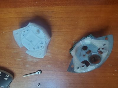
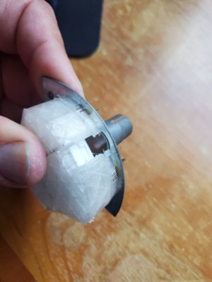
stepperHousingApart.jpgstepperHousing.jpgGaugesApart.jpgGaugesTogether.jpg
Gauge housings designed in CAD and 3D printed in clear PLA to allow instrument lights in and around. I got a donor set of gauges from Carl at La Jolla independent just in case I ever want to go back...?

valveCoverLogo.jpgskinnedBoxTop.jpgblueBoxLeftSide.jpgblueBoxBack.jpgblueBoxFront.jpgcoolantTest.jpgboxDrop.jpgboxSkinnedIn.jpg
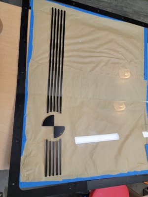
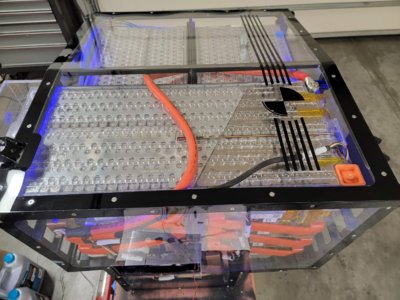
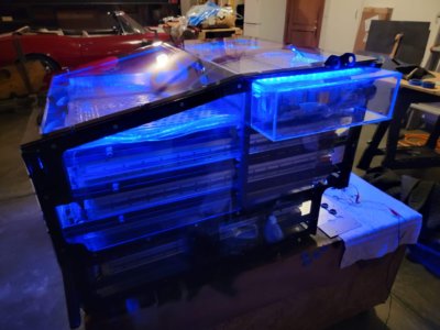
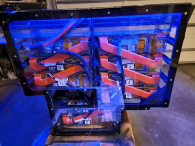
Front battery box "fish tank" skinned in clear acrylic with valve-cover inspired CSE logo and edge banding on inside with vinyl cut on my wife's craft plotter. Blue LEDs are hidden in top rail. All HV and BMS wiring completed but 3-port coolant manifolds are temporary and will be replaced by 10-porters. The box is a tight fit in the car.

brakeLineHoles.jpgbrakeLineRight.jpgbrakeLineRightSplit.jpgbrakeLineLeftSplit.jpgbrakeLineRear.jpgbrakeAndPS.jpgpsRes.jpgbrakeAndPSLines.jpgpsBanjoToAN.jpg
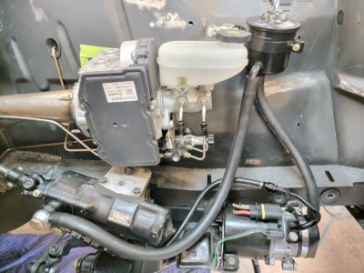
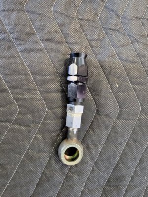
Brake and power steering lines complete (sans clamps). Required a lot of customization, including converting stock banjo high pressure fitting to AN and same on Mini Cooper pump. Stainless lines from master to prop valve, copper/nickel everywhere else. Hopefully this crowd appreciates the use of the original vintage reservoir. Still need to wire up the booster and pump.

ACHoses.jpgACHosesToBulkhead.jpgACPorts.jpg
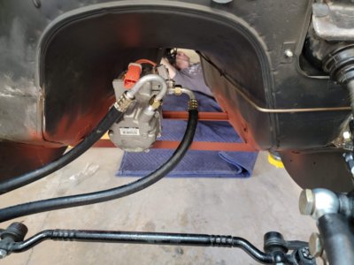
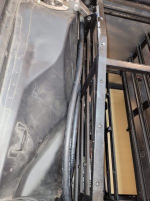
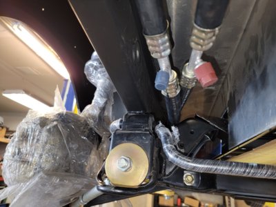
AC hoses built and run to bulkhead connectors on firewall. Service ports are located down low due to limited space. Forgot to take photos of condenser/dryer but it is all typical, with dryer behind right headlights.

HVLinesToDU.jpgOBCLayout.jpgbatteryBriefcase.jpgbatteryBriefcaseClosed.jpg
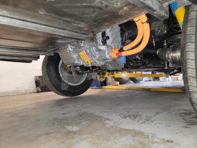
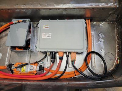
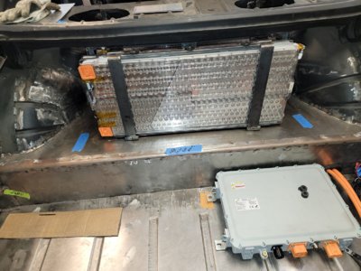
High voltage lines run from trunk to Tesla drive unit. Onboard charger/DC-DC converter placed and coolant lines run through trunk to under car. Ingenuous rear battery rack has three batteries stacked under the package shelf and then one more mounted vertically in a hinged "briefcase" that allows all 4 to be fit and racks removed for servicing.
 
Back
Top