Fixing that little rust spot...

eriknetherlands

Moderator
Site Donor
Messages
2,753
Reaction score
1,993
Location
Netherlands, Eindhoven area
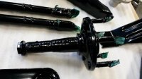
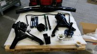
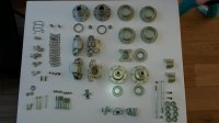
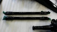
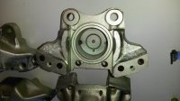
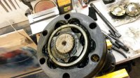
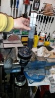
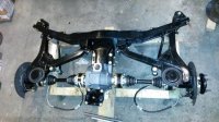
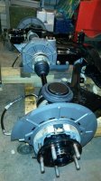
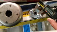
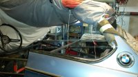
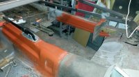
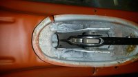
now pics of the shiny bits & pieces

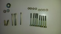
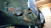
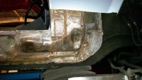
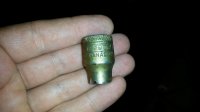
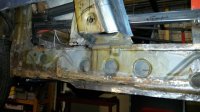
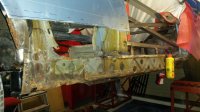
After sandblasting all parts that fitted in my small cabinet, I dropped of the parts to be yellow zinc coated. It would be powder coating for the large chassis parts with some rust protection underneath the powder coat.

I was told that the chassis components are not ideal to be zinc coated first, as they have welded joints that can retain the acid. This acid will leach out after the zinc treatment, eating away the fresh zinc, giving instant rust at places where you really don't want it; along/in the weld seems.

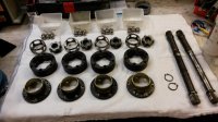
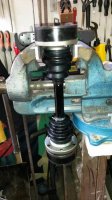
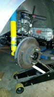
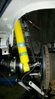
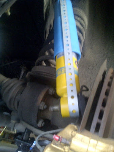
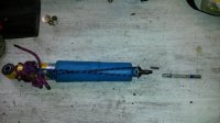
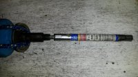
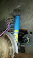
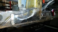
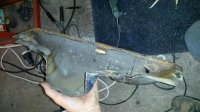
So I choose to have them sandblasted, and then metal sprayed with a 95%Zinc 5% Alu coating, and then powder coated. This additional Zinc-Alu coat layer is the protection against rust in the event of stone chips, and the unavoidable installation dents & nicks. Its a thick coating compared to Zinc plating, about 0,2 mm and quite tough; you need a sharp chisel to get it off.

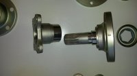
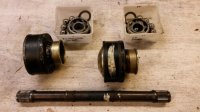
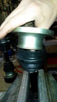
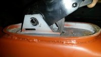
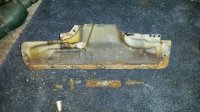
I happened to get the Zinc+Alu coating onto the oil sealing flange of the stub axles (my bad masking); that was not a good idea. I had to put them on a lathe to get the surface to look like clean steel again.

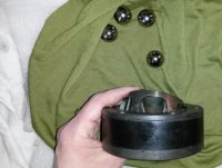
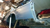
But how big is the smile when you go and pick them up? :D

fyi; all done for 250 euro's for the black parts, and 60 euro's for the yellow zinc bits.
 

Attachments

  • 20150130_125701-01.jpg
    20150130_125701-01.jpg
    65.9 KB · Views: 360
  • 20150130_125653-01.jpg
    20150130_125653-01.jpg
    86.6 KB · Views: 378
  • 20150206_135755-01.jpg
    20150206_135755-01.jpg
    60.7 KB · Views: 352
  • 20150130_125704-01.jpg
    20150130_125704-01.jpg
    55.2 KB · Views: 330
  • 20150206_135803-01.jpg
    20150206_135803-01.jpg
    67.8 KB · Views: 325
  • 20150206_135818-01.jpg
    20150206_135818-01.jpg
    38.3 KB · Views: 330
  • 20150206_135824-01.jpg
    20150206_135824-01.jpg
    37.1 KB · Views: 326

eriknetherlands

Moderator
Site Donor
Messages
2,753
Reaction score
1,993
Location
Netherlands, Eindhoven area
half shafts

Dismantled the haft shafts.

Marked them 1 through 4, counting from right to left (dunno why i choose that logic..)


Remarkable, i found that the cages that retain the balls can be mounted in 2 ways. One side is flat ("vlak" in dutch...), the other has a more pronounced facetted side.
3 cages were mounted with the flat side towards the spindle end (C-clip side of the axle; 3rd pic); 1 cage was mouned with the facetted side up (second pic).....

Was this how it left the factory, or was it rebuild already once before?

I rebuild them, just the way I found them.
 

Attachments

  • 20141214_233407-01.jpg
    20141214_233407-01.jpg
    72.5 KB · Views: 299
  • 20141213_215733-01.jpg
    20141213_215733-01.jpg
    83 KB · Views: 306
  • 20141213_222213-01.jpg
    20141213_222213-01.jpg
    57.2 KB · Views: 294
  • 20141213_221829-01.jpg
    20141213_221829-01.jpg
    79.1 KB · Views: 306
Last edited:

eriknetherlands

Moderator
Site Donor
Messages
2,753
Reaction score
1,993
Location
Netherlands, Eindhoven area
half shaft rebuild

some tricks i used for the assembly.


I pushed the dust boot over the axle. The yellow zinced collar fits inside the dust cover. You can easily get it to fit by using your thump, pushing from the inside on the rubber boot, pushing it over the edge.

assemble the outer ring with cage & balls.

Next install the disc spring & assy with the balls. Place the C-clip. To knock the steel caps on to the CV joint, i used a rubber hammer. Don't hit the steel collar itself; build it upside down, suspend it on a vise (see pic) and hammer on the steel outer ring of the CV joint.

I used silicone to seal the inner and outer caps to the CV joint and prevent leakage.
 

Attachments

  • 20150307_132117-01.jpg
    20150307_132117-01.jpg
    50.8 KB · Views: 370
  • 20150307_222126-01.jpg
    20150307_222126-01.jpg
    81.4 KB · Views: 361
  • 20150307_134258-01.jpg
    20150307_134258-01.jpg
    63.5 KB · Views: 384
  • 20150307_121511-01.jpg
    20150307_121511-01.jpg
    59.8 KB · Views: 352
  • 20150307_222447-01.jpg
    20150307_222447-01.jpg
    99.8 KB · Views: 359

Peter Coomaraswamy

Well-Known Member
Site Donor $$
Messages
3,787
Reaction score
896
Location
Austin, TX
Erik, very nice indeed, I hated doing the CV joints- I think I still have that black grease on me somewhere! Nice step-by-step too!
 

eriknetherlands

Moderator
Site Donor
Messages
2,753
Reaction score
1,993
Location
Netherlands, Eindhoven area
2 Bilstein rear damper questions

Hi, just 2 questions on Bilsteins;

1. I purchased them from W&N some time ago. can anyone decipher from the codes if these are these "sport" or "HD" type? What would be the difference?
( i am trying to figure out what risk i run of punching out my strut towers, and if i preemptively need/want to weld my towers. They were OK up to now with the old red dampers...)

2. the Bilsteins come with 2 rubbers and 2 washers. The rubbers+washers seem to be incorrect for the E9 rear as the hole in the tower is roughly 23 mm, the Bilstein washers have a 17 mm protorusion. ditch the Bilstein rubbers & washers?

(Depicted are the tower replacement caps that I got from a German forum member, a new W&N top mount rubber and the bilsteins with supplied rubbers & washers.)
 

Attachments

  • 20150308_212920-01.jpg
    20150308_212920-01.jpg
    37.9 KB · Views: 303
  • 20150308_213216-01.jpg
    20150308_213216-01.jpg
    52.8 KB · Views: 310
  • 20150308_213302-01.jpg
    20150308_213302-01.jpg
    54.1 KB · Views: 332

Stevehose

Well-Known Member
Site Donor $$
Messages
12,984
Reaction score
5,657
Location
Sarasota, FL
Not sure about Sport/HD but I read somewhere that Bilstein only makes one style now. They have a responsive cust service so maybe worth an inquiry.

Definitely ditch the Bilstein bushings and use the BMW one with a washer top and bottom, plus the inner metal sleeve.
 

eriknetherlands

Moderator
Site Donor
Messages
2,753
Reaction score
1,993
Location
Netherlands, Eindhoven area
How to get this aligned?

Steve, thanks for your hint. I am installing the upper bushings as you advised.

I am however running into the next problem; how to line up the lower end of the Bilstein damper to the stud. See pictures. The angle is so far off, that if I would use a big hammer, the edge of the sleeve in the damper would just eat right into the thread of the stud.

Shortening of the springs with a spring compressor did not work sofar. The springs are compressed up the point that there is only 1cm between the spirals. I don't dare to compress them further (or can I?)

What am i doing wrong here?

Erik
E9 3.0 CS May 1973.
 

Attachments

  • 20150403_211458_resized.jpg
    20150403_211458_resized.jpg
    97.1 KB · Views: 318
  • 20140916_214833.jpg
    20140916_214833.jpg
    92.3 KB · Views: 307

Stevehose

Well-Known Member
Site Donor $$
Messages
12,984
Reaction score
5,657
Location
Sarasota, FL
You have to compress the shock, mount it on the bottom bolt, then let it uncompress up through the tower hole. I made one out of plumber's metal but a rope or something similar will work. Install one of the washers on the shock before releasing the shock up through the rubber and sleeve mounted in the tower.

IMG-20110812-00500.jpg


Steve, thanks for your hint. I am installing the upper bushings as you advised.

I am however running into the next problem; how to line up the lower end of the Bilstein damper to the stud. See pictures. The angle is so far off, that if I would use a big hammer, the edge of the sleeve in the damper would just eat right into the thread of the stud.

Shortening of the springs with a spring compressor did not work sofar. The springs are compressed up the point that there is only 1cm between the spirals. I don't dare to compress them further (or can I?)

What am i doing wrong here?

Erik
E9 3.0 CS May 1973.
 

12doplumbing

Well-Known Member
Messages
156
Reaction score
0
Location
Windsor California
I am inspired! You are a stud, Eric. And thank you for posting, in all minutiae, all the steps and frustrations -- I get hung up on one little item, over think it, dwell, read, whine, post, and basically procrastinate. Glad to see you at least have this tendency as well.
Really beautiful job.
 

Attachments

  • image.jpg
    image.jpg
    93.2 KB · Views: 331

HB Chris

Well-Known Member
Site Donor $$
Messages
19,418
Reaction score
8,759
Location
Huntington Beach, CA
Steve's approach is best but I have done top first and tapped lower mount over the bolt, it didn't damage the threads.
 

eriknetherlands

Moderator
Site Donor
Messages
2,753
Reaction score
1,993
Location
Netherlands, Eindhoven area
rear damper installation

Followed your advise; thanks because the damper and I were quite stuck.

Hammering didn't work. Full blow didn't move anything.

So tried the method compressing it before installation.

Tied it down, and let it uncompress inside the wheel well. It expanded alright, but i didnot control it that well. It shooted just besides the rubber bushing, missing the hole. And then it jammed to the "ceiling' of the strut tower.
It's a pain in the ass to get it compressed again to fit it rightly though the hole of the rubber bushing. I needed to fit my hand in there, next to the damper, and grab with two and a half fingers the top of the damper.

So on the next attempt, I extended the length of the damper by inserting a hex bit, and a hex pipe tool (see pics); I used these as guidance. The shock couldn't miss the rubber anymore. Much easier.

Then with the rope, it's easy to control the speed of the extending shock. No sweat anymore, its basically then a one hand operation.

She's on four wheels again!

next steps; attach the doors & align. weld internal reinforcements before cutting out the lower wings, sills, seat supports, rear axle support points and the 4 floor sections. and likely some other small rust spots (around the rear window i found some already) as we go along. Then welding it back up again, and getting it to a paint shop. I guess it's another winter in the garage....

Erik.
 

Attachments

  • 20150406_141208-01.jpg
    20150406_141208-01.jpg
    74.5 KB · Views: 407
  • 20150406_141238-01.jpg
    20150406_141238-01.jpg
    89.3 KB · Views: 395
  • 20150406_144310-01.jpg
    20150406_144310-01.jpg
    76.6 KB · Views: 398
  • 20150406_112711-01.jpg
    20150406_112711-01.jpg
    64.7 KB · Views: 401
  • 20150406_144316-01.jpg
    20150406_144316-01.jpg
    77.8 KB · Views: 418

Gransin

Well-Known Member
Site Donor
Messages
1,529
Reaction score
1,272
Location
Vasa, Finland
next steps; attach the doors & align. weld internal reinforcements before cutting out the lower wings, sills, seat supports, rear axle support points and the 4 floor sections. and likely some other small rust spots (around the rear window i found some already) as we go along. Then welding it back up again, and getting it to a paint shop. I guess it's another winter in the garage....

Erik.

It probably will be another winter in the garage (or 2), but it's worth it, isn't it ;-)
I hope that you don't find too much rust inside the sills on the reinforcement piece, and around the lower "B"-post. Or maybe you have checked inside them already? That and the rear axle support points are the worst places to work with I guess, floors and seat supports are easy to do in comparison.

And really good work! Keep it up!
 

eriknetherlands

Moderator
Site Donor
Messages
2,753
Reaction score
1,993
Location
Netherlands, Eindhoven area
1 or 2 years; time will tell.

This is how the body looks now...

Let's see how much time i can spend, and how effective I can be.
Maybe the biggest trial is to try and not get distracted by the (poor) state of the parts that come off.

focus, focus, focus....
 

Attachments

  • 20150311_214815.jpg
    20150311_214815.jpg
    63.7 KB · Views: 421
  • 20150311_214935-01.jpg
    20150311_214935-01.jpg
    57.4 KB · Views: 414
  • 20150311_214830-01.jpg
    20150311_214830-01.jpg
    63 KB · Views: 515
  • 20150311_214917-01.jpg
    20150311_214917-01.jpg
    83.6 KB · Views: 426
  • IMG-20120310-00053-01.jpg
    IMG-20120310-00053-01.jpg
    58.6 KB · Views: 419

eriknetherlands

Moderator
Site Donor
Messages
2,753
Reaction score
1,993
Location
Netherlands, Eindhoven area
Handbrake lever, can it actually be removed?

I am in the process to replace the 4 floor pan sections, rear subframe mounting points and the sills. I'll upload some pics tomorrow, but one thing had me scratching my head yesterday evening:

I would like to remove the handbrake lever to inspect the area for rust and cracks, as it is a notorious area i understood.


However, having detached and removed the cables, the switch and the pivot axle, the push pin with rod+spring, tthe handbrake lever itself cannot go upward throught the hole. At the bottom of the handbrake lever are two "banana shaped" curved steel pieces that guide the steel handbrake cables. The witdh of these 2 "banana's" are more then the width of the hole in the interior. I wigled the handbrake all directions, but to no avail. also the toothed ratchet part is still inside.

Can the handbrake actually be removed?


- the tech books just say 'detach the cables and drive out the pivot axle, and remove".

- Would the handbrake lever need to be removed from the underside, vs what i expect (towards the interior)? The underside has a cover that seems to be welded on from below. I guess it can't go out that way either.

- I am aware of the Dequincey /Paul Cain upgrade thread, but there I could not find the answer to my question.


Has anyone have been succesful in getting it out?

(My car is a stock '73 CS)

Regards, Erik.
 

eriknetherlands

Moderator
Site Donor
Messages
2,753
Reaction score
1,993
Location
Netherlands, Eindhoven area
handbrake removal; how to get it out?

I want to remove my handbrake lever, but i can't get it out.

I've seen coupe pictures undergoing resprays, where the handbrake lever is removed... so it can be done.

The 4rth picture shows the topview; where you can see the black steel "C" shape being wider then the hole. Any tricks (or bolts) that i am missing here?

( as well 2 pictures of the project that will keep me off the couch for the next 2 years)

Erik.
 

Attachments

  • 20150818_214929.jpg
    20150818_214929.jpg
    92.4 KB · Views: 338
  • 20150818_215048.jpg
    20150818_215048.jpg
    95.5 KB · Views: 324
  • 20150818_215300.jpg
    20150818_215300.jpg
    96.2 KB · Views: 313
  • 20150818_214904.jpg
    20150818_214904.jpg
    96.5 KB · Views: 313

eriknetherlands

Moderator
Site Donor
Messages
2,753
Reaction score
1,993
Location
Netherlands, Eindhoven area
Turns out my car is worth more then i thought

Found this in the inner b-post when i hacked it off.
Its a 9mm socket by respectable brand "Gedore".

At least the PO had a good tool set. Well, he had. He's missing one.

If you are the owner of this 9mm socket, please report yourself. Be prepared for some questions though....

Besides that, i was surprised by how good the inner sill actually is.
Nevertheless it will be removed to be sandblasted and coated before being welded back in. It's too good to substitute for a non-original.

Removing the intermediate sill also allows inenr sill (that is on the interior side) to be treated on both sides, and to replace the rusted front and rear sections of that panel as well.

The Lower B post part that is cut out will be sandblasted, coated and welded back in later as well.

- still looking for a way to remove the handbrake by the way. Anyone?
Erik.
 

Attachments

  • 20150825_223643.jpg
    20150825_223643.jpg
    95 KB · Views: 361
  • 20150825_223803.jpg
    20150825_223803.jpg
    98.3 KB · Views: 356
  • 20150823_205947.jpg
    20150823_205947.jpg
    91 KB · Views: 359
  • 20150825_223854.jpg
    20150825_223854.jpg
    101.8 KB · Views: 344
  • 20150825_223926.jpg
    20150825_223926.jpg
    94.1 KB · Views: 336
  • 20150825_225011.jpg
    20150825_225011.jpg
    96.8 KB · Views: 330
Last edited:

Stevehose

Well-Known Member
Site Donor $$
Messages
12,984
Reaction score
5,657
Location
Sarasota, FL
Well that explains the mysterious rattle! Try contacting Gransin, in his resto pics the handle is off.
 

Gransin

Well-Known Member
Site Donor
Messages
1,529
Reaction score
1,272
Location
Vasa, Finland
- still looking for a way to remove the handbrake by the way. Anyone?
Erik.

If I remember correctly, this is how you remove it:

1. Push the handbrake lever-lock upwards.

2. When the lock is out of the way, push the lever all the way forward, or as much as possible.

3. This might require some brute force, as the "banana shaped" curved steel pieces tend to bend outwards a bit over time, and becomes wider than they were originally. But the lever should pop out of there with enough force.

Hope that helps :)


Top