Fixing that little rust spot...

eriknetherlands

Moderator
Site Donor
Messages
2,751
Reaction score
1,993
Location
Netherlands, Eindhoven area
Setup for working at the underside

Just for documentation purposes; someone may find this usefull.

my dilemma was the following:

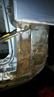
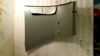
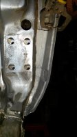
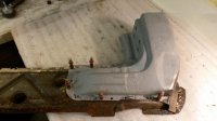
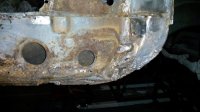
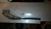
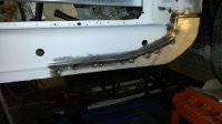
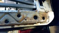
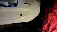
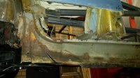
- I want to clean the underside from old undercoating and some rust spots & and have good acces to my sills.
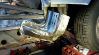
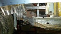
- I have only a small lift available, going up about 90 centimeters; 3 foot or so. This lift however has a centre frame that covers the whole center axis of the car; from drain plug to drainplug. It leaves no acces to exhaust, drive shaft bearings, large parts of the floor sections etc.
- My engine is still in as i don't have the space to park it....

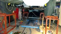
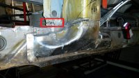
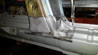
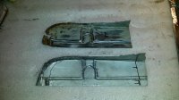
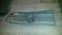
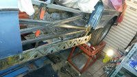
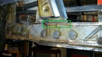
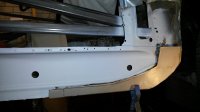
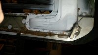
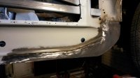
Now to replace the sills, I reinforced the body with an internal frame as the standard practise to keep the rigidity; It turned into half a roll cage.

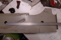
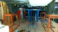
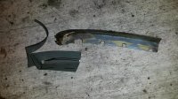
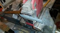
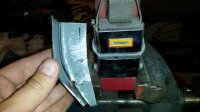
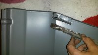
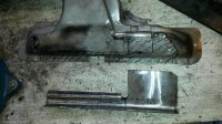
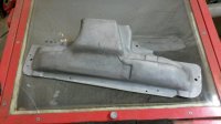
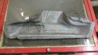
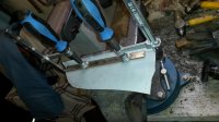
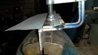
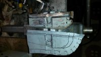
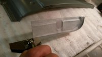
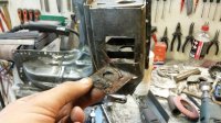
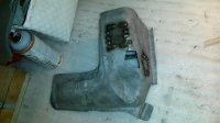
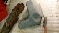
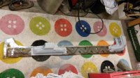
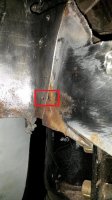
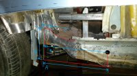
Now the ensure this was done right and level, I constructed 4 steel 'blocks' that support the wheels, they are just over 60cm (2 foot) high. I levelled the 'blocks' with a laser so that each wheel is on a level surface.

Turned out my garage floor is more then 3 cm off from horizontal.

Hopefully all the effort will pay off in doors that will show a good fit without endless 'adjustments' later on.

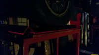
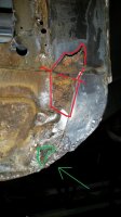
The pictures had to be made in the dark, because it just a crappy 30 euro laser and the red line doesn't show on a photo unless the lights were switched off.....

Erik
 

Attachments

  • 20150809_233419.jpg
    20150809_233419.jpg
    97.7 KB · Views: 386
  • 20150809_234041.jpg
    20150809_234041.jpg
    99.5 KB · Views: 391
  • 20150809_233450.jpg
    20150809_233450.jpg
    89.3 KB · Views: 360
  • 20150809_234121.jpg
    20150809_234121.jpg
    91.1 KB · Views: 393

eriknetherlands

Moderator
Site Donor
Messages
2,751
Reaction score
1,993
Location
Netherlands, Eindhoven area
I finally got my stuck handbrake lever out of the transmission tunnel

with help from Gransin, who pointed me in the right direction.

He mentioned that the bottom of the handbrake lever tends to widen itself over time. (the banana shaped curved section that gently guides the handbrake cable around the corner).

In my case this was indeed what happened, as the width of the handbrake lever was about 2 to 3 mm's more then the hole in the transmission tunnel.

With Gransin's argument, I was convinced that force was needed. That always helps you get over that question, with crowbar in hand, "Is this really necessary?"... and you step back thinking there must be other ways. After ten minutes of staring in turns at your crow bar and your coupe you approach him/her again thinking "Do I really want to do this? "
So that's were the hints are helpfull: Yes force is needed, Yes you really need to do this. Indeed serious force was needed; I was afraid of bending the lever in the middle while puling if left and right.

After removing the handbrake lever, it clearly showed some widening, one of the welds holding the two halves together had partly seperated. The banana shaped curved section was sandwiched in a vise to narrow it down a bit more, needed some taps with a hammer and some pliers to get them parallel and straight again. a small, flat weld at the bottom prevents it from widening ever again.

Result is one fresh handbrake lever with new paint, and more important: better acces to the top of the transmission tunnel.

Thanks for the hints.

Photo is from the handbrake as removed. Note the non symetric sides.
 

Attachments

  • 20150920_223337.jpg
    20150920_223337.jpg
    88.3 KB · Views: 311

eriknetherlands

Moderator
Site Donor
Messages
2,751
Reaction score
1,993
Location
Netherlands, Eindhoven area
support frame and first sill parts cut out

I've posted some questions in the past months on details, but it has been a long time since there was an update from my side on the real problem on my car; the rust.

There is quite some rust on the panels that make the sills and pillars, but none is beyond repair.
It's ofcourse relative; A body shop would likely replace it with new sheet metal from BMW or W&N, but my hours are hobby anyway.
I am the type of guy that wants a job to be perfect. I want to keep the panels as original as possible.
So I try to salvage the panels if i can. Copy every crease and fold in the sheets. Weld all parts flush. Grind every weld untill even. Check with a torch if there are holes in the welds. My ultimate goal is a non-identifiable repair.
It's however not always wise or feasible; there are some stupid constructions (rust traps) and sometimes its simply not possible to gain acces with an angle grinder.
Luckily none of the panels required sections larger then 40 cm (~1 foot)... up to now.

I started by Welding in a supporting structure:
(the connection of the rear subframe mounting points left to right was already in since 2012)
- connecting A-pillars to parcel shelf
- connecting A-pillars left o right
- supporting the inner sills from sagging downwards when removing A, B and C pillar lower ends.
- providing a height reference for floor replacements


First pictures are when I start exposing pillars and sills.
1; 215213 inner reinforcement structure
2; 212737 rear wing removal
3; 212854 showing rust on the vertical connection piece linking the B-pillar to outer panel
 

Attachments

  • 20150818_215213.jpg
    20150818_215213.jpg
    97.7 KB · Views: 363
  • 20150821_212737.jpg
    20150821_212737.jpg
    92.1 KB · Views: 364
  • 20150821_212854.jpg
    20150821_212854.jpg
    94.3 KB · Views: 355

eriknetherlands

Moderator
Site Donor
Messages
2,751
Reaction score
1,993
Location
Netherlands, Eindhoven area
and on with the sills

Since then, I hacked off lower front and rear wings, and the A-B and C- piller bottom parts.
These three pillar parts are 2mm thick steel sheet and easy to weld.
I took out these a/b/c pillar elements one by one, drilling 3mm positioning holes through the component and its supporting element before drilling out the spot welds.
The 3 mm holes will be used for positioning the panels later when building the sill back up again. (using Cleco's, the spring type clamps. They will show up on the pictures in due time)

Only then did I drill out the spotwelds to actually remove the part.
Sandblasted them to get a view on where the holes would be.
In the parts where the rust had stolen the strength, I put in new sections.
Sandblasted them again & treated with rust converter, sandblasted again and coated in 3 layers of epoxy.

I found out that replacing rust with 2 mm thick steel is actually good workout if you want nice flush fitting panels.
I told my dear wife that I had picked up a sport; it wasn't wat she hoped for...
After I tack in a patch with a few small welds, I check the alignment of the part on the supporting element. Corrections for fit are then quite easily done; some pulling, pushing or hammering usually is enough to get it flush.
In some cases I was not happy with the dimensions / fit, so I cut it out and start over again before fully welding the seems through and through.

so before actually cutting out the B-pillar, I wanted to remake the bottom part of the vertical panel that connects the B-Pillar to the outer body panel
1; first start of panel beating; showing old part and new blank
2; hole for easier forming of curves
3; trim excess material
4; use shrinking tool to get a flowing curve
5; tada: a curve!

Now it was onto the horizontal sill parts.
 

Attachments

  • 20150825_200854.jpg
    20150825_200854.jpg
    98.9 KB · Views: 330
  • 20150825_201042.jpg
    20150825_201042.jpg
    99.5 KB · Views: 298
  • 20150825_201253.jpg
    20150825_201253.jpg
    99.4 KB · Views: 314
  • 20150825_201405.jpg
    20150825_201405.jpg
    98.2 KB · Views: 319
  • 20150825_201707.jpg
    20150825_201707.jpg
    90.2 KB · Views: 338
Last edited:

eriknetherlands

Moderator
Site Donor
Messages
2,751
Reaction score
1,993
Location
Netherlands, Eindhoven area
further pics

1; superimpose old part on new and draw edge.
2; Trimmed further & fit check in outer skin panel of rear wing (old piece with rust hole visible)
3; lining up new section
4; simple jig for welding, made with original part. Cut old part and place new section in same position.
5; fully welded; half grinded
6; old and renewed
7; fit check was OK; After this check I could cut out the B-pillar.
8; sandblasted and epoxied; C'est fini. it will be in the shelf waiting to be welded back in
 

Attachments

  • 20150825_202310.jpg
    20150825_202310.jpg
    98.1 KB · Views: 320
  • 20150825_205126.jpg
    20150825_205126.jpg
    93.9 KB · Views: 320
  • 20150825_205638.jpg
    20150825_205638.jpg
    99.1 KB · Views: 314
  • 20150825_210753.jpg
    20150825_210753.jpg
    97.9 KB · Views: 322
  • 20150825_211742.jpg
    20150825_211742.jpg
    99 KB · Views: 316
  • 20150825_214922.jpg
    20150825_214922.jpg
    98.4 KB · Views: 322
  • 20150825_215310.jpg
    20150825_215310.jpg
    82.9 KB · Views: 321
  • 20150827_232018.jpg
    20150827_232018.jpg
    86.1 KB · Views: 330

eriknetherlands

Moderator
Site Donor
Messages
2,751
Reaction score
1,993
Location
Netherlands, Eindhoven area
B-Pillar cut out

B-Pillar

1 B-pillar cut location ; note also the 3 spot welds in the red area. Here the reinforcement is tucked under the panel on the interior side of the vertical B-Pillar panel. You have to drill the 3 spotwelds, and bend the tab of the panel upwards to allow for the removal of the lower part.
2 old and replacement panel
3 welded and sandblasted B pillar, outside view. Note also that i added 2 drain holes on the front and rear edge of the part. I believe the original centre one allows for water to puddle in the corners.
4 inside view B-pillar after welding.
5 welded B pillar and testfit

It was satisfactory for me, so now its on to the A-pillar.
 

Attachments

  • 20150825_223643.jpg
    20150825_223643.jpg
    95.6 KB · Views: 486
  • 20150828_143250.jpg
    20150828_143250.jpg
    99 KB · Views: 337
  • 20150906_000814.jpg
    20150906_000814.jpg
    93 KB · Views: 321
  • 20150906_000825.jpg
    20150906_000825.jpg
    94.3 KB · Views: 322
  • 20150831_151519.jpg
    20150831_151519.jpg
    92.1 KB · Views: 458
Last edited:

eriknetherlands

Moderator
Site Donor
Messages
2,751
Reaction score
1,993
Location
Netherlands, Eindhoven area
remake A-pillar connection piece

This part is exposed when you remove the Front wing.
It's actually a longer part, and runs all the way up to the windshield.
In the bottom, where it is welded to the A-pillar it creates some nice semi closed area's and crevasses.
It is also in the direct line of fire of all stones and water coming from the front wheel. So it has had a tough life.

(isn't it called a 'door jamb' in the US?)

1 cut out rusted A-pillar connection piece
2 new layout
3 start with flange
4 made a jig to make the flange
5 hammer in the depressions
6 made the 90 degree bend, and curve at the bottom needs 2 welds.
7 welded bottom corner & finished the curve
8 test fit in front wing
9 test fit on A-pillar
10 Finished and sandblasted; before epoxy painting.

now that this part was finished, I put it aside and started to remove the A-pillar.
 

Attachments

  • 20150831_155737.jpg
    20150831_155737.jpg
    95 KB · Views: 327
  • 20150831_155819.jpg
    20150831_155819.jpg
    91.3 KB · Views: 319
  • 20150831_161847.jpg
    20150831_161847.jpg
    95.7 KB · Views: 318
  • 20150831_161955.jpg
    20150831_161955.jpg
    93.3 KB · Views: 309
  • 20150831_163941.jpg
    20150831_163941.jpg
    93.2 KB · Views: 300
  • 20150903_215223.jpg
    20150903_215223.jpg
    98.2 KB · Views: 316
  • 20150904_145352.jpg
    20150904_145352.jpg
    97.4 KB · Views: 313
  • 20150903_225335.jpg
    20150903_225335.jpg
    93.2 KB · Views: 329
  • 20150903_224728.jpg
    20150903_224728.jpg
    96.5 KB · Views: 328
  • 20150905_212921.jpg
    20150905_212921.jpg
    91.9 KB · Views: 325

eriknetherlands

Moderator
Site Donor
Messages
2,751
Reaction score
1,993
Location
Netherlands, Eindhoven area
Onwards with the A-pillar removal

The process to expose the rot on the whole sill, front to back, is starting to be like peeling an union. There are more similiarities then it just having layers.
After removal the part is fixed up and treated so it can be reunited with the car at a later stage.

1. A-pillar removal; spotwelds drilled & sliced off. Take care not to cut into either of the 2 horizontal reinforcements inside the A-pillar!
These horizontal reinforcements locate the vertical plate with the 4 threaded holes that position your doorhinge. If you dislocate the position of the door hinge bolts, then getting a good panel fit will be challenging. Check for the spotwelds on the outside of the A-pillar surface to determine your cut.
2. cut out 2 old repairs. I hope my welding is more appreciated then this 'hedge hog'
3. B-pillar with holes. The rust actually started in the location where there are openings.
One is a hole for body wax application, the other spot was an opening where a speednut was located.
Why was there ever a speednut? Also the W&Nesch parts have these holes and speednuts inserted here, but nothing is attached to it as far is I know.
Ideas anyone of the purpose of this speednut?
4. remains of the speednut and it's opening, and a plate welded by PO on top.
5. two of three patches in place
6. last patch, a lip for welding the reinforcement to the sill; actually a bit shaped different then original.
I choose to close the original opening in the reinforcement piece that allowed the underlying intermediate sill to protude from under it towards the wheelwell.
This means that now I have one component less that is exposed to stones from the wheel intermediate sill
7. testfit with A pillar to intermediate sill
 

Attachments

  • 20150904_151720.jpg
    20150904_151720.jpg
    98.5 KB · Views: 323
  • 20150904_155718.jpg
    20150904_155718.jpg
    98.1 KB · Views: 329
  • 20150904_155840.jpg
    20150904_155840.jpg
    95.1 KB · Views: 324
  • 20150904_160230.jpg
    20150904_160230.jpg
    98.6 KB · Views: 324
  • 20150907_215606.jpg
    20150907_215606.jpg
    95.7 KB · Views: 329
  • 20150923_222627.jpg
    20150923_222627.jpg
    92.7 KB · Views: 306
  • 20150923_232815.jpg
    20150923_232815.jpg
    69.9 KB · Views: 318

Gary Knox

E9 Member Emeritus
Site Donor $$
Messages
1,821
Reaction score
743
Location
West Chester, Pennsylvania
Erick,

MOST impressive work. You have great metal working skills, and thank you so much for showing us what you are doing and how you are doing it.
 

eriknetherlands

Moderator
Site Donor
Messages
2,751
Reaction score
1,993
Location
Netherlands, Eindhoven area
Intermediate sill (rocker) removal; Progress

Thanks for your kind words Gary. I'm learning as i go; welded the thick stuff first: the inner support frame, the red boxes that I placed under the wheels, and now the 2mm material that makes up the sill parts. It forced me to play around with my MIG welding machine and get the practice hours.

Nevertheless I am stilll dreading the day that i * have to * start welding on the outer panels; that weld will be staring me in the face for years if i get it wrong. And never a day passes that i wonder if I ever get my doors to fit ever again...
Oh, and did i mention that I also found rust behind the glove box...? I can peek into the "Pandora" box.

I'm glad it's my hobby and i don't have to pay anyone to do it.

With the repairs to the lower A-pillar completed, I could go on peeling back the layers making up the sill (rocker). Some pics of the progress

1. intermediate sill showing the how and why of this action. I believe all these panels are all original. Nothing of this was visible in any way on the outside of my car...no bubbles, nothing. Even with the sill covers removed it looked clean & straight.

2. Here you can see that the inner sill is actually made up out of the long sill, and a small extension of about 10cm (4 inch) at the front; it's the shiny bit. The intermediate sill and this extension overlap by about 4-5 cm (2 inches). Here you see (in the middle of the picture, red lined) a flap that I cut of the front end of the long sill part and folded upwards, looking into this gap; This is the best rust trap ever.. In green there is actually the footwell ventilation.

I suspect this was done by BMW because they used the pressing tools they had already for the 2000cs, and with the new E9 being *2 cilinders* longer, they needed to add some length.
BMW was almost bankrupt at that time, and I can imagine they choose this option. Survive as a company was more important then a surviving e9 I guess.
An effect of this is that close to the wheel well, this double sheet construction is a sure place for failure.
Once moisture is trapped between there it cannot dry up, thus it will continue to rust for a long time. It had.
This double sheet construction is not coming back; it will be integrated in one piece with the sill.

3. Drilling out of spotwelds & removal of intermediate sill
4. Don't forget that the intermediate sill is tucked under a lip of the inner panel that makes up the vertical B-pillar.
You need to drill the spotwelds on that lip (in the green box), and bend the lip upwards to get the sill from out uder threre.
5. Just for visualisation; left is rear of car, right is front; A-pillar. Never mind the carpet.

Erik.
 

Attachments

  • 20150906_004942.jpg
    20150906_004942.jpg
    97 KB · Views: 330
  • 20150906_005012.jpg
    20150906_005012.jpg
    98.2 KB · Views: 325
  • 20150906_005820.jpg
    20150906_005820.jpg
    99.1 KB · Views: 451
  • 20150825_223926.jpg
    20150825_223926.jpg
    94.4 KB · Views: 455
  • 20150923_232650.jpg
    20150923_232650.jpg
    97.7 KB · Views: 338
Last edited:

eriknetherlands

Moderator
Site Donor
Messages
2,751
Reaction score
1,993
Location
Netherlands, Eindhoven area
The following steps were in this order:
After removal of the intermediate sill I replaced the front edge of the inner sill.
I wanted to get the inner sill straight and whole again, as i want to weld in the floors panels in before welding back the intermediate sill. When I will start welding the floor sections I need to remove the grey paint from the inside of the both sides of the inner sill to give a clean surface to weld to. after welding, you need to clean and coat the welds again.
If you would have the intermediate sill back on, you can't reach the back of the weldspots anymore.

Another reason for doing the inner sill first was that is just a flat plate, so alignment is easy; flat to the rest.

210521 new front edge of inner sill
211002 new and old (note the PO repair to the floor section with a 'sheet-on-rust-construction' in the middle of the picture near the reflection. You can also see clearly the holes in the orginal sill (rocker) panel.
223448 Inner sill repair tacked in place
234303 testfit intermediate sill to check repair to underlying inner sill
000025 test fit with A pillar
229534 welded through inner sill repair.
221242 Same as new, but bettter (less rust trap)!
 

Attachments

  • 20150918_210521.jpg
    20150918_210521.jpg
    87.5 KB · Views: 345
  • 20150920_211002.jpg
    20150920_211002.jpg
    90.6 KB · Views: 332
  • 20150920_223448.jpg
    20150920_223448.jpg
    87.6 KB · Views: 332
  • 20150923_234303.jpg
    20150923_234303.jpg
    97.8 KB · Views: 464
  • 20150924_000025.jpg
    20150924_000025.jpg
    89.6 KB · Views: 441
  • 20150926_220534.jpg
    20150926_220534.jpg
    89.5 KB · Views: 331
  • 20150926_221334.jpg
    20150926_221334.jpg
    90.4 KB · Views: 344
Last edited:

eriknetherlands

Moderator
Site Donor
Messages
2,751
Reaction score
1,993
Location
Netherlands, Eindhoven area
Question on replacement inner sill (rocker) panel dimension & shape

Looking for assitance of someone who happens to have a replacement part lying around and willing to take some measurements.

I noticed in my car that rust was developing between the inner sill and the outer half of the rear wheel well. so i want to seperate them to be able to clean the rust, and as the inner sill in that area has a simple shape, I want to cut of the last 20 cm and replace it with virgin steel.

But here's my dilemma; the drawings in the BMW partslist show a different shape in that area of the inner sill compard to the photo's of Walloth&Nesch. What shape is correct?
The BMW drawing shows that the end of the inner sill has a vertical, 90 degree fold. The picture of W&N shows a flat end.

Question 1; Is there a 90 degree bend or not? I am suspecting that W&N is correct; their panel fit with other parts I purchased is spot on.
Question 2. Can someone who happens to have a replacement part of W&N or BMW take a picture of the rear end of the inner sill and possibly measure up some dimensions for me? See attached pic for dimensions i'm looking for A,B,C and D. Also i'd like to know if the end is straight (red line) or a curve (green line).


Attached some pics of the current condition;
1. as found when peeling the intermediate sill
2. removed the reinforcement piece
3. picture showing rust creeping between the inner sill (panel behind) and the panel of the rear wheel well (panel in front). A 3 mm hole was drilled through the 2 plates before seperating, for exact relocation with Cleco's later. So the rust around the rear hole is actually between the 2 panels. In my view, restoring car without removing this rust is not effective.
4. picture showing the dimensions i'm looking for.
5. Pic of W&N part without the 90 degree bend ( at least i think there is none) ...
6. Pic of BMW drawing from parts books, with a 90 degree bend in the red circle.

Thanks in advance.
 

Attachments

  • 20150906_011002.jpg
    20150906_011002.jpg
    96.5 KB · Views: 382
  • 20151006_000107.jpg
    20151006_000107.jpg
    97.1 KB · Views: 366
  • 20151006_000249.jpg
    20151006_000249.jpg
    98.6 KB · Views: 349
  • Inner sill current condition with q's.jpg
    Inner sill current condition with q's.jpg
    98.2 KB · Views: 372
  • picture of WandN website with actual part showing flat end.jpg
    picture of WandN website with actual part showing flat end.jpg
    11.9 KB · Views: 352
  • picture of BMW parts bookwith 90 degree corner at the line to number nine.jpg
    picture of BMW parts bookwith 90 degree corner at the line to number nine.jpg
    20 KB · Views: 328
Last edited:

Bmachine

Well-Known Member
Site Donor $
Site Donor $$
Messages
3,533
Reaction score
1,790
Location
Northern California coast
This is so incredibly interesting. Well written, well photographed, well welded...

Thank you Erik.

PS. I'm sorry I don't have the answer to your question but I'm sure someone will soon.
 

Peter Coomaraswamy

Well-Known Member
Site Donor $$
Messages
3,787
Reaction score
896
Location
Austin, TX
Not Sure

Hi Erik, I think that 45 degree tab ends up covering the lowest part of the seam in the rear wheel arch. On my 72 there is a strange flange that seems to be a patch/afterthought but looks "factory". I will try to take a picture for you tomorrow. Also, I could be way off-
 

eriknetherlands

Moderator
Site Donor
Messages
2,751
Reaction score
1,993
Location
Netherlands, Eindhoven area
Another question on orignal sheet metal shapes

I was wondering how the underside of the passenger floor looks like. (see link)
- I have seen pictures of Vranedom were there are 2 elements under the floor.
- I have pics of the BMW museum car in Munich, but only of the drivers side, not the passenger side. (see attached photo)

http://vranedom.com/rockers/P6200014.JPG


The pic form the BMW museum (green car) shows the driver side. Unfortunatly i don't have a passenger side pic. Drivers side shows 3 plates under the floor: 1. A green flange, 2. a square plate with sides and 3. a 3rd black flange protecting the fuel and brake lines.
This matches closely the sitation of Vranedom, although it being the other side.

The question...
Is the condition of Vranedom's car, having part 1, the flange and 2. the square plate on the pass side representative of all models (US/European, build year, fuel return line presence, engine etc) ?

Erik
 

Attachments

  • PC050094left front.jpg
    PC050094left front.jpg
    97.1 KB · Views: 323

afeustel

Well-Known Member
Site Donor $
Messages
551
Reaction score
177
Location
Houston
Both the 72 Bav and the 73 CS have the same configuration as shown in your images. That is to say that the drivers and passenger side are identical, except that the drivers side has the extra plate that protects the fuel lines.

Others may have comments with respect to other year CS models.
 

eriknetherlands

Moderator
Site Donor
Messages
2,751
Reaction score
1,993
Location
Netherlands, Eindhoven area
Thanks for the answers & a cliffhanger

Peter, if you happen to have the pics from your car (of the rear end of the inner rocker/sill), then i am still interested.

Afeustel; thanks for your answer regarding the bits under the driver and passenger floor. Now I know how to make this part of the underside to look like the factory condition.

I think I will remake the parts, but not weld them on. To risky with regards to rust traps. I am considering to glue them on, after the epoxy coat that I put on all bare steel.

Again, thanks for the added homework ;-)

In the meantime all the compliments about my metal working skills got me overconfident; I found my limits.... I did a **** job trying to fit in a new rear right floor panel. I cut the W&Nesch replacement part too small for the gap I already had in the body. It resulted in a 4-5 mm gap in some places, the pictures tell it a bit. The gap in the top centre and top left corner (first pic) cost me the most time. Never mind the gap towards the front of the car (right side of first pic). A W&N front floor panel will be fitted straight against the new W&N panel.
I found out I am terrible in trying to weld such a gap shut.....I am at it already 3 evenings trying to make it into a nice flowing curve. amp settings (to high), torch distance (to close), to much gas (blowing the soft metal away). I was helped by youtube; Let's say it's a learning curve.

I also found out that the panels from W&N are off by 10 mm in some places. Thats kind a hard to sweep under the carpet and make it disappear. But that's a cliffhanger for my next post.
Erik.
 

Attachments

  • 20151020_233729.jpg
    20151020_233729.jpg
    88.5 KB · Views: 324
  • 20151021_012535.jpg
    20151021_012535.jpg
    92.8 KB · Views: 318
Last edited:

Peter Coomaraswamy

Well-Known Member
Site Donor $$
Messages
3,787
Reaction score
896
Location
Austin, TX
Hi Erik,

almost in the center of the picture is the tab that I think is folded over and welded in place. I think that is what you were asking about. Hope this helps.
 

Attachments

  • erik.jpg
    erik.jpg
    87.4 KB · Views: 333

chaggawagga

New Member
Messages
2
Reaction score
0
inner sill measurements

Hello Erik,

absolute top job you are doing there. I read your posts with great interest.

Regarding the requested measurements on the back end of the inner sills, here are your answers (I took your questions as an excuse to slip out to the man cave last night ... :D):

Measurements were taken from a genuine BMW NOS inner sill panel I happen to have lying around.

A = 350 mm (to the cut out at the bottom)
B = 360 mm
C = 50 mm
D = 180 mm (total height, there are cut outs both at the top and the bottom)

The BMW part does have a 90° bend at the end which ist straight and not rounded. So in your photo 'green' applies and not 'red'. In that respect, the BMW parts catalog drawing is correct.

If you want more measurements taken on this part, just let me know.

Hope that helps and do keep up the good work :wink:
 

Attachments

  • E9_inner_sill_panel_re.jpg
    E9_inner_sill_panel_re.jpg
    89.3 KB · Views: 327
Last edited:

eriknetherlands

Moderator
Site Donor
Messages
2,751
Reaction score
1,993
Location
Netherlands, Eindhoven area
Thanks to Chaggawagga

for the dimensions of the inner sill !
Exactly what i need!

This allows me to continue with it, and do it respectfully.

can't wait to finish work here and be back in the garage...
 
Top