Some help getting engine started

When I replaced a starter on my former 2002 I left the 12:00 wire connected and the ballast was cherry red. I removed it immediately and all was good.
 
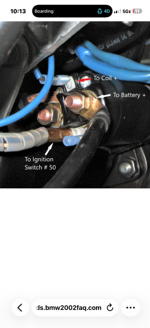
Scott, i was wondering the same thing until Chris mentioned that in new starters, the 12:00 pole is hot all the time. we know the 3:00 is hot all the time - where the battery connects and the 6:00 is triggered by the ignition switch.

so this is something that i learned today ... i had no idea that the other side of the solenoid was hot all the time.
Well, then that would not be a good place to attach the coil to because it would drain the battery, since the coil would always be energized regardless of the ignition switch
 
I recently watched my friend try to start his vw bug after he installed a brand new pertronix equipped distributor.

Poof! Puff of smoke. If you supply voltage backwards I believe it’s destroyed.

When I removed the pertronix module to inspect it was easy to see the tell tale plastic tape was melted.

I saw replacement modules on Amazon for 35 dollars.

YMMV. Good luck!
 
It is hot when ignition is on only.
Are you sure about that? How does the starter know that the ignition is on? As I understand the diagrams, there are only three wires: One from the battery, one from the ignition switch START bus (controlled by the START contact of the ignition switch), and one to the starter motor itself. Is there a fourth wire from the RUN/IGNITION bus?
 
Here is a photo that someone on the 2002 forum posted with the new-style starter (SR44xx). This one shows wire to coil going from that 12:00 spot. Question I suppose is whether it’s hot truly “all of the time” or only when ignition keyed on. When I had black/red wire to ballast hooked up to that 12:00 the ballast got red when key was turned to any “on” position so I would suspect the latter. I’m also assuming that I want to run wire to coil from that spot, as shown. But again, going to confirm all of my wire colors and match up to schematic since the CSi seems to have slight variation
 

Attachments

  • IMG_9196.png
    IMG_9196.png
    1.3 MB · Views: 25
Trust me it is hot with ignition on! I don’t know what that terminal would be used for. On the old starter it is only energized when cranking to bypass the ballast.

Why would you run a wire from there? The green wire is in front of the radiator. The CSi is no different from a CS.
 
from Don’s post earlier, and confirmed when he was walking me through this a week ago via FaceTime, there does seem to be some difference in the wiring since there’s a wire running to the computer and to the cold start relay that is part of this circuit. As he noted, I need to find the djet schematic and make sure I know what goes where. Once I understand that, the question will be mapping that “original” wiring onto this new-style starter. Once I have it figured out I’ll be sure to post the solution here so the next person isn’t struggling the way I am.
 
as i see in the 2002 pic - the 12:00 wire is black / red ... which would go to the coil. that wire follows the same path in the harness as the green wire - along the radiator wall.

since JC wanted to look at d-jet diagrams - the blue book has a few different things.
there is an overall 3.0cs / csa / csi (61-0/42+ 43) that doesn't really show d-jet
1779641931640.png

1779641998616.png


there is 61-0/38 + 39 which shows the wiring of the d-jet
1779641657760.png

1779641683791.png


there is a d-jet blowup 61-0/45 (which follows the USA 3.0cs (with wipe + wash interval)
1779641393281.png
 
Need to spend a bit more time here but I already have one answer - the wire that I also have hooked up to the battery 30 is to the main relay, as shown here
 
its good to study the diagrams ... i have learned a lot going through my engine compartment harness and migrating it with Don's megasquirt harness ... mostly from Don's instructions, but studying where i had things to remove was helpful.
 
Trust me it is hot with ignition on! I don’t know what that terminal would be used for. On the old starter it is only energized when cranking to bypass the ballast.

Why would you run a wire from there? The green wire is in front of the radiator. The CSi is no different from a CS


The top stud is hot. It has a black/green wire going to it on later Motronic models
 
so I’ve been studying the schematics since @rsporsche was kind enough to post them. So as I understand it, turning key on to second position but not to “start the engine” activates the ballast resister along the green wire. When you twist the key to actually start the engine, the ignition circuit sends signal to post 16 of starter along black wire, from 168 (plug connector) to starter (27). Attached to starter on post 30 is battery in and black wire out to main relay (162), from which power is sent on to the fuel injection system which would appear to be an “always on” connection. Twisting the key to start position activates post 16 pulling in the solenoid and connecting battery to post 50, which then send signal directly to the ignition coil along black/red wire.
So at the moment I do NOT have any black/red wire connected to my starter. I have ignition circuit in on post 16 (6:00 position) and battery and main relay connection on the same post 30 terminal. If on the new starter that 12:00 position is hot all of the time, then what serves as the switched-on post to which the connection to the starter attaches? In other words, on these new starters what does activating the solenoid do in terms of turning on one of the contacts? I thought that turning the key activated the starter and concurrently activated the ignition coil to then go through the work of activating distributor.

In looking through some on the 2002 forum who have used the SR444x or 441x starter, they have removed that black/red wire from starter to coil and instead have run a wire from (in their case) fuse 12 to the coil. That is an ignition-activated fuse so turning key to start sends signal to starter to turn and then concurrently sends direct signal to ignition coil rather than going through starter. I suppose I could create the same setup, just need to determine what wire would correspond to that ignition-switched wire that I can run to ignition coil.
 
Last edited:
There seems to be a great deal of confusion here.

Let's get some terms in place so we can all be on the same page.

The car has FOUR power modes, and while in the E9 they are not labeled as such, there are four power buses (lines that are powered from the battery via the fuse block based the position of the key switch:
BATT (always on) (Red wire)
ACC (only on in the accessory/run position of the key switch)
RUN (sometimes called IGNITION) (green wire)
START (the momentary mode when you turn the key to start the car)

In your car, with no ballast resistor, the coil should be powered from the RUN bus. The coil does not care where that comes from, but it should be powered when the key is in the run position. (easy to test).

I have no idea what the extra (12:00) pole on the starter is for. Unless there its a RUN wire to the starter (which would require FIVE terminals: START, BATT, Starter Motor, RUN, and the mysterious 12:00 pole), then the starer would have no way to control that 12:00 post so it was only on when the key was in the RUN position. I'd check this just to be sure, but I suspect it is either hot all the time, or it is only hot when the key is in the START position (because there is no other wire to cause it to know the system is in the RUN mode).

The solenoid is powered in the START mode. In that mode the solenoid pulls in the pinion gear and activates the starter motor.

I don't know what other signals the CSI ECU might need, but since there are only these five modes, one would think the ECU would really only care about the RUN mode, and maybe the START mode (more on this below).

In terms of starting, I don't know exactly how the D-Jet handles this, but the L-Jet has a cold start valve (CSV) and a "thermo time switch). The CSV is activated by the START signal, and it squirts gas into the intake when the engine is cranking. The Thermo-Time switch tells the ECU when the engine has been running for some time period OR when the engine is warm, so it can control the mixture accordingly (richer for some period after a cold start, but not if the engine is already warm...).

I'd highly recommend getting a copy of Probst, which explains all of the Boach EFI systems is great detail.
Probst Electronic Fuel Injection Book
 
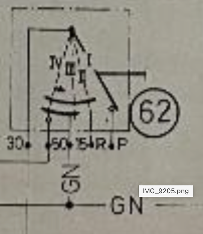
Thank you Scott, that helps for terminology. Here’s where I am having some issue understanding the schematic. In looking at the ignition switch in picture 1, I see 4 positions which I would assume from right to left are off, acc, run, start. In my reading ACC powers green wire and thus ballast and on to coil. When turning to START, I am seeing the circuit which I described above and outlined here in blue (picture 2). This is obviously all on the original E9 starter. That circuit seems to be a connection made between post 30 and 16 (12:00) by the solenoid being activated on START.
I understand your point that the coil can be powered in RUN mode by connecting the green wire directly to positive terminal of coil and leaving out the ballast since my coil doesn’t need it. Is that better/different than powering coil through black/red wire in START mode? The original starter seemed to have both connections as per the schematic. If I’m understanding your point, since the coil only needs 12v but doesn’t care how it gets it, I can leave out the black/red wire from starter to coil that would have been energized on START and just connect green wire. When I turn key to the START position, however, is that green wire still energized? This is where my reading of the schematic falls short, since I’m not sure whether the ignition circuit represents discrete independent circuits or whether they are “additive”, ie position ACC turns on some items, RUN is ACC plus more and then START is ACC plus RUN plus START. The latter makes sense intuitively, since things don’t turn off when once moves from RUN to START, but just want to confirm.
And thank you all for helping me through this. Most of the other wiring changes or adaptations I’ve made have been fairly straightforward and don’t involve this much complexity so this is forcing me to expand my knowledge - a good thing.
IMG_9205.png
IMG_9207.jpeg
IMG_9207.jpeg
 
I like the blue line!

“. In my reading ACC powers green wire and thus ballast and on to coil”

Nope- ACC is not power to ballast or coil.
Accessories are powered ie radio violet wire

Run powers coil green wire unless you have a 1974 model where is no green wire or ballast resistor as it is replaced by ballast wire.

Note you must have a white wire by coil from harness to resister OR a green wire at booster area connected to a green white wire for the main relay to turn on (early vs late harness)
IMG_6642.jpeg
 
Last edited:
Unfortunately, this is not the clearest diagram. (Seems to have been drawn by some German guy...)


From left to right you have OFF, ACC, RUN and START. The curved dark traces represent the actual contact ts inside the switch (AMHIK - since I pulled my 635 switch apart by accident when removing it!!!)

The angled line represents the wiper inside the switch. You can see that one end is connected to BATT (wire 30). As the key rotates, that wiper moves clockwise from position I to position II it first encounters the ACC trace (pin R). I have no idea why there is no wire shown there). So in this position all of the accessories are powered. In position III it encounters the RUN trace, and energizes Pin 15, which is the GREEN wire (G=Grun). You will note that the ACC trace is still energized in position III. This is because you do not want the accessories turning off in the RUN mode*.. In position IV, the wiper encounters the tiny little START trace, and energizes pin 50 which is the BLACK wire (SW=Schwarz)), that goes to the starer solenoid via junction 168.
Screenshot 2026-05-25 at 7.08.05 AM.png

* These power modes OFF, ACC, RUN, START are cumulative. OFF is off, ACC powers accessories (wipers, turn signals, radio, etc), RUN powers ACC and all of the ignition related elements, and START powers ACC, RUN and the starter. This is critical because you need accessories to work when the engine is running, and starting, and you need the ignition to be on when the engine is running or starting.
The exceptions to this are big power consumers like the headlights. These get separately de-powered by the UNLOADER RELAY which turns off certain heavy loads in the START mode.

Some comments on your statements/questions (IN ALL CAPS)

"In looking at the ignition switch in picture 1, I see 4 positions which I would assume from right to left are off, acc, run, start. CORRECT.

"In my reading ACC powers green wire and thus ballast and on to coil." NO. ACC POWERS PIN R, WHICH ACCORDING TO DON IS A VIOLET WIRE.

"When turning to START, I am seeing the circuit which I described above and outlined here in blue (picture 2). This is obviously all on the original E9 starter. That circuit seems to be a connection made between post 30 and 16 (12:00) by the solenoid being activated on START." CORRECT. THE START POSITION POWERS THE BLACK WIRE WHICH ENERGIZES THE SOLENOID. THIS CLOSES THE CIRCUIT TO THE STARTER MOTOR, AND IN THE DIAGRAM ALSO CLOSES THE CRICUIT FROM THE BLACK WIRE TO PIN 16 OF THE STARTER, WHICH IS CONNECTED TO THE BLACK AND RED WIRE. IN THIS CASE THAT BLACK AND RED WIRE GOES TO THE COIL DIRECTLY, EFFECTIVELY SHORT CIRCUITING THE CIRCUIT FROM THE GREEN WIRE TO THE BALLAST RESISTOR AND TO THE COIL.

"This is where my reading of the schematic falls short, since I’m not sure whether the ignition circuit represents discrete independent circuits or whether they are “additive”, ie position ACC turns on some items, RUN is ACC plus more and then START is ACC plus RUN plus START. The latter makes sense intuitively, since things don’t turn off when once moves from RUN to START, but just want to confirm." CORRECT. THEY ARE ADDITIVE.

Now in a ballast resistor case, it is important to note that the "bypassing" of the ballast resistor occurs by effectively short circuiting the resistor.

Resistors in parallel have the following resistance:

Rp=R1R2/(R1+R2), so you can see that if R1 is zero, then the total resistance is zero, regardless of what R2 is. This is what occurs when the solenoid energizes the black and red wire. In START mode the solenoid energizes the black and red wire which applies 12V to the coil. The green ignition wire is still energized, but since that passes through the resistor, which is effectively short circuited by the black and red wire, the ballast resistor is meaningless.
Here is a diagram showing the current flow in both modes. You can see that the red line is in parallel withe green line, and since the red line has zero resistance (or nearly so), the green path is effectively bypassed.

Screenshot 2026-05-25 at 7.50.39 AM.png


In your case, since there is no ballast resistor, you can just power the coil from the green wire, and eliminate the black/red wire. This also avoids routing the black and red wire from the starter to the coil (as @HB Chris has been saying). Just leave the odd 12:00 lug on the starter disconnected.
 
Makes perfect sense, and a reminder to me not to post after 11 PM, since I incorrectly identified the ACC position as power by green instead of the RUN, which you and Don corrected.
One slightly random question then, to which I have been looking online for an answer. The usual coils take 12V to power and want lesser voltage while running so as not to wear out points, etc, and thus the purpose of the resister. As you noted, when I turn the key to START I am electrically bypassing that resister and delivering the full 12V. In the new green wire direct to coil system, I deliver 12V at all times and the coil internally resists. In what way does it achieve these two states of full or partial voltage, or is it always delivering a lesser voltage on to the distributor? In an electronic distributor like the pertronix this may not matter I suppose but aside from the simplicity of one circuit vs two I fail to see the advantage of the single circuit if you’re running points since it would seem you get less spark.
When at home later today I’ll confirm my wiring. The main issue I have been having is not getting a spark from the large black output wire from coil to distributor cap. I also should check to make sure that the inner contacts of that wire are making contact with the terminal in the center of the coil, and then you’ve given me (in previous post in this thread) a way to electrically check my connections with a multimeter. I will get it solved!
 
I am not familiar with coils that have an internal ballast. Unless that ballast was switched in some way, it would be easier to just have a lower tension coil, since that is effectively what you will get if there is an internal ballast resistor that is not switched.

At any rate, the Pertronix should withstand the coil kickback without any resistor.

I am still perplexed by your issue with a red-hot ballast resistor. That implies some heavy current flow through the coil and Pertronix unit. So I'd do some of the resistance checks I outlined above. It may be that there is a wiring error or a shorted coil that is causing your no-spark issue. My money would be on the coil, since there are not that many wires to mix up, and none of them that I am aware of would short the coil primary to ground.
 
Back
Top