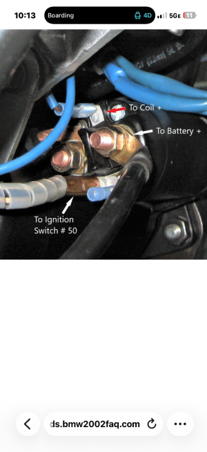
Unfortunately, this is not the clearest diagram. (Seems to have been drawn by some German guy...)
From left to right you have OFF, ACC, RUN and START. The curved dark traces represent the actual contact ts inside the switch (AMHIK - since I pulled my 635 switch apart by accident when removing it!!!)
The angled line represents the wiper inside the switch. You can see that one end is connected to BATT (wire 30). As the key rotates, that wiper moves clockwise from position I to position II it first encounters the ACC trace (pin R). I have no idea why there is no wire shown there). So in this position all of the accessories are powered. In position III it encounters the RUN trace, and energizes Pin 15, which is the GREEN wire (G=Grun). You will note that the ACC trace is still energized in position III. This is because you do not want the accessories turning off in the RUN mode*.. In position IV, the wiper encounters the tiny little START trace, and energizes pin 50 which is the BLACK wire (SW=Schwarz)), that goes to the starer solenoid via junction 168.
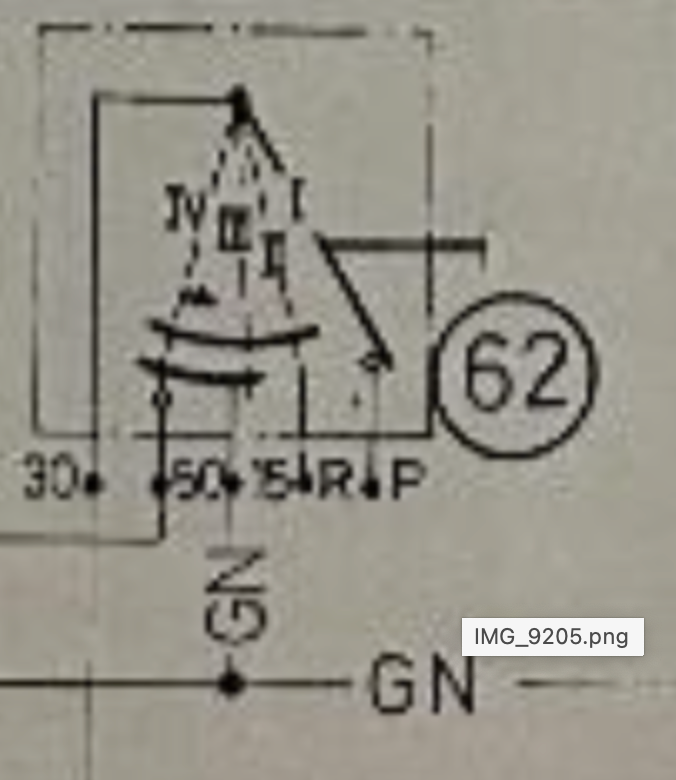
* These power modes OFF, ACC, RUN, START are cumulative. OFF is off, ACC powers accessories (wipers, turn signals, radio, etc), RUN powers ACC and all of the ignition related elements, and START powers ACC, RUN and the starter. This is critical because you need accessories to work when the engine is running, and starting, and you need the ignition to be on when the engine is running or starting.
The exceptions to this are big power consumers like the headlights. These get separately de-powered by the UNLOADER RELAY which turns off certain heavy loads in the START mode.
Some comments on your statements/questions (IN ALL CAPS)
"In looking at the ignition switch in picture 1, I see 4 positions which I would assume from right to left are off, acc, run, start. CORRECT.
"In my reading ACC powers green wire and thus ballast and on to coil." NO. ACC POWERS PIN R, WHICH ACCORDING TO DON IS A VIOLET WIRE.
"When turning to START, I am seeing the circuit which I described above and outlined here in blue (picture 2). This is obviously all on the original E9 starter. That circuit seems to be a connection made between post 30 and 16 (12:00) by the solenoid being activated on START." CORRECT. THE START POSITION POWERS THE BLACK WIRE WHICH ENERGIZES THE SOLENOID. THIS CLOSES THE CIRCUIT TO THE STARTER MOTOR, AND IN THE DIAGRAM ALSO CLOSES THE CRICUIT FROM THE BLACK WIRE TO PIN 16 OF THE STARTER, WHICH IS CONNECTED TO THE BLACK AND RED WIRE. IN THIS CASE THAT BLACK AND RED WIRE GOES TO THE COIL DIRECTLY, EFFECTIVELY SHORT CIRCUITING THE CIRCUIT FROM THE GREEN WIRE TO THE BALLAST RESISTOR AND TO THE COIL.
"This is where my reading of the schematic falls short, since I’m not sure whether the ignition circuit represents discrete independent circuits or whether they are “additive”, ie position ACC turns on some items, RUN is ACC plus more and then START is ACC plus RUN plus START. The latter makes sense intuitively, since things don’t turn off when once moves from RUN to START, but just want to confirm." CORRECT. THEY ARE ADDITIVE.
Now in a ballast resistor case, it is important to note that the "bypassing" of the ballast resistor occurs by effectively short circuiting the resistor.
Resistors in parallel have the following resistance:
Rp=R1R2/(R1+R2), so you can see that if R1 is zero, then the total resistance is zero, regardless of what R2 is. This is what occurs when the solenoid energizes the black and red wire. In START mode the solenoid energizes the black and red wire which applies 12V to the coil. The green ignition wire is still energized, but since that passes through the resistor, which is effectively short circuited by the black and red wire, the ballast resistor is meaningless.
Here is a diagram showing the current flow in both modes. You can see that the red line is in parallel withe green line, and since the red line has zero resistance (or nearly so), the green path is effectively bypassed.
In your case, since there is no ballast resistor, you can just power the coil from the green wire, and eliminate the black/red wire. This also avoids routing the black and red wire from the starter to the coil (as
@HB Chris has been saying). Just leave the odd 12:00 lug on the starter disconnected.