
72 3.0 CS 2240344 Restoration

Interesting update Scott.

I have been acquiring the parts for this. I have a 3.0cs pod to use as a donor, I assume that the fuel gauge is good, not sure of the temperature gauge. I also picked up a 911 gauge (have sent two back as the oil pressure portion did not appear to work). I have a third 911 gauge and it too has an oil pressure gauge (right side of the gauge pod) that does not move when variable voltage is applied.

Using the same DC power supply that I use for plating I am able to get the fuel gauge to work across its range, but oil pressure gauges just nudge a little off the needle and then will not react.

I will need one of the right hand gauges (either BMW temp or Porsche oil) to work. I was starting to think that my testing process was in error...

Any insight on oil pressure gauge function would be great. I have not taken any of the gauges apart yet, just testing the Porsche gauges to make sure that they will work while they are still within the warranty or exchange period.
 
Interesting update Scott.

I have been acquiring the parts for this. I have a 3.0cs pod to use as a donor, I assume that the fuel gauge is good, not sure of the temperature gauge. I also picked up a 911 gauge (have sent two back as the oil pressure portion did not appear to work). I have a third 911 gauge and it too has an oil pressure gauge (right side of the gauge pod) that does not move when variable voltage is applied.

Using the same DC power supply that I use for plating I am able to get the fuel gauge to work across its range, but oil pressure gauges just nudge a little off the needle and then will not react.

I will need one of the right hand gauges (either BMW temp or Porsche oil) to work. I was starting to think that my testing process was in error...

Any insight on oil pressure gauge function would be great. I have not taken any of the gauges apart yet, just testing the Porsche gauges to make sure that they will work while they are still within the warranty or exchange period.
Hi Lance. The oil pressure gauge is also a bit odd. It is expecting a resistance at the G input. So put 12 volts on the + terminal, ground the case, and put a resistor to ground on the G terminal. The resistance should go between 10 ohms and 180 ohms
 
Good idea to try out the gauges. I also bought one of the porsche ones and have been following your project since I have really found my additional "below the radio" gauges useful, but since I'm considering adding AC that spot won't be available anymore, and you and I both know that I'm not giving up the dash speaker spot after all the work we did getting a nice speaker and mount in there! My clock, well, that I can afford to lose.
 
Here is the Oil Pressure setup. To test the meter, you have to connect it to 12 volts and ground, and then connect a variable resistor between 10 and 180 ohms to the G terminal..

Screenshot 2026-09-02 at 4.35.26 PM.png
 
Here are some pics of my 911 meter in the BMW gauge withthe revised gauge face. This is using the above test circuit with resistors connected between the G terminal and ground. And yes, I recognize that I have the gauge pod upside-down...

10 Ohms
Screenshot 2026-09-02 at 5.38.02 PM.png


32 Ohms
Screenshot 2026-09-02 at 5.39.17 PM.png


100 Ohms
Screenshot 2026-09-02 at 5.39.05 PM.png
 
Looks very nice! Can you show a photo of how you actually have this wired? I get plugging 12v into positive and then grounding, but how are you creating the variable resistance - in the oil pressure gauge I understand that the pressure is driving a change which is then transmitted down the wire to the G terminal, but not sure how you’re doing that here - multimeter? Resister?
 
Looks very nice! Can you show a photo of how you actually have this wired? I get plugging 12v into positive and then grounding, but how are you creating the variable resistance - in the oil pressure gauge I understand that the pressure is driving a change which is then transmitted down the wire to the G terminal, but not sure how you’re doing that here - multimeter? Resister?
See the circuit above. The only change between these images is the value of a resistor between the G terminal and ground. This mimics what the pressure sender does.

So I am basically just simulating the pressure sensor with various resistances to gound.

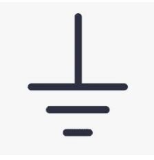
So just hook up 12 volts to the + terminal, ground to the little metal spade with the ground symbol (see below), and put a 100 ohm resistor between the ground terminal and the G terminal. The needle should move by about 2/3 of the scale.Screenshot 2026-09-03 at 7.35.55 AM.png

To better understand how this works, let's look at the circuit again...

Screenshot 2026-09-02 at 4.35.26 PM.png

Here we have the meter with its internal resistors. The meter movement is pretty much like all meters, a small electro magnetic motor, only it doesn;t rotate continuously. There are many ways to make this, but the simplest would be to place a small magnet on a spindle that is connected to the needle. A fixed coil is wrapped around that armature so that it is close, but doesn't touch the armature. The armature has a small clock spring that causes it to sit at the zero position (stopped by some barrier, like a small pin.

When current passes through the coil, it creates a magnetic field, and this causes the magnetic armature to move in order to align with the field. However, this alignment is stymied by the clock spring so the armature and needle only move to the point where the force from the magnetic field is equal to the force from the spring. Add more current, you get more force and the needle moves farther. Add less current and the needle moves back toward zero.

The key observation here is that the thing that causes the meter to move is CURRENT.

So, since the 12 volts applied to the top of the above circuit is fixed, we need a way to control the current. That is done by changing the resistance value at the G terminal. If that resistance is low lots of current flows, and if it is high, little current flows.

Now, I can read your mind and you are wondering how, if low resistance cases higher current, then what is low resistance causing a small meter movement, and higher resistance (lower current) is causing a higher meter movement.

I believe what is actually happening here is that there are two current paths. One is fixed, and causes current to flow though the main coil to ground. The other goes from +12 through the wire wounds resistor and, I believe, through a second coil that is wound in the other direction from the main one. The result is that as more current flows in the external resistor, the second coil creates a magnetic field that CANCELS THE PRIMARY ONE. And this reduces the force on the armature. Like this:

Screenshot 2026-09-03 at 8.06.49 AM.png


I think they do this for two reasons:

First, the opposing fields tend to damp out any motion on the needle, since the armature is sort of trapped in a low spot between two fields. This reduces meter jitter as the car moves.

Second, it is easier to calibrate the meter this way. The wire wound resistor in the meter is clearly adjusted by adding or removing turns on the spool, so they can apply a fixed resistor in manufacturing, see where the needle goes , and the adjust that by adding or removing wire to get the needle to the right spot. This negates any variation in magnetism in the armature, and any variability in the clock spring from unit to unit.

You can see this small wire wound resistor in the photo below (this is the gas gauge, hence the little black diode I discussed in the long post above), but the meters are sort of made the same way.

Screenshot 2026-09-03 at 7.59.08 AM.png
 
Last edited:
My impression from some rudimentary research is that the wire wound resistor is also a temperature compensating element. Reportedly, the wire it's made from has a different temp/resistance curve than plain copper wire so readings stay accurate as temps fluctuate.

It seems old oil pressure gauges are prone to failure, I've seen a lot posted for sale in non-working condition and the Porsche one I got doesn't respond to simple voltage application, but now I've seen the light and will have to hook it up as explained above by Scott to see if it has some life.
 
My impression from some rudimentary research is that the wire wound resistor is also a temperature compensating element. Reportedly, the wire it's made from has a different temp/resistance curve than plain copper wire so readings stay accurate as temps fluctuate.

It seems old oil pressure gauges are prone to failure, I've seen a lot posted for sale in non-working condition and the Porsche one I got doesn't respond to simple voltage application, but now I've seen the light and will have to hook it up as explained above by Scott to see if it has some life.
Temp compensation would make sense. The gauges seem more complicated than one would expect, and I suspect that is to address real world automotive application challenges, like temp and vibration. VDO has been making automotive instruments for a long time, and I would expect that they have reached a fairly high level of development.

That said, I can't see much that could go wrong with one since there are few things to fail... two windings, a couple of resistors and a spring...Might be worth examining a "dead" one to see if maybe there is a broken solder joint or something. The wires to the coils are very fine...

If yours doesn't work, either send it to me or I'll drop by and pick it up when I am in town for the F1 GP in October. Perhaps I can repair it..
 
Got some new Zener diodes in the mail today. I was able to confirm that the best setup for using the gas gauge to measure voltage is an 8.2 volt zener between the meter and the G terminal, and a 240 ohm resistor in the + line. No ground to the case is needed.
 
OK. All my chassis stuff is off at the powder coaters. Will be done next week.

Subframes, struts, trailing arms, etc. Then I can finally start re-assembling things!

Plan to do some 2K epoxy painting of the small parts this weekend.
 
Last edited:
Preparing to paint the CV joints. A couple of questions:
1Are the yellow zinc caps painted? The ones on the boot side were painted, but the others were not. The replacements are silver zinc and not painted, but the boots are pre-installed. My preference would be to leave these unpainted.

2 what is the best way to strip the CV barrel? The paint on them is pretty rough, and I’d rather not try to paint over it. Paint remover and a scraper? Seal them up with duct tape and bead blast, followed by thorough cleaning?
 
Last edited:
Scott, someone has to say this, but I am in awe of your stamina, relentlessness, engineering savvy, and enthusiasm, only dwarfed by your regular and comprehensive postings teaching the rest of us, how you are solving your latest E9 puzzle. Keep it up, it is very inspiring! Mike
Thanks Mike!
It all so interesting, and I am pleased if I can contribute a bit to the enormous body of knowledge represented by this forum.

Sometimes I wonder if I am posting too much and am crowding out the voices of others, If anyone feels that way LMK, and I'll slow down.

S
 
Last edited:
Interesting update Scott.

I have been acquiring the parts for this. I have a 3.0cs pod to use as a donor, I assume that the fuel gauge is good, not sure of the temperature gauge. I also picked up a 911 gauge (have sent two back as the oil pressure portion did not appear to work). I have a third 911 gauge and it too has an oil pressure gauge (right side of the gauge pod) that does not move when variable voltage is applied.

Using the same DC power supply that I use for plating I am able to get the fuel gauge to work across its range, but oil pressure gauges just nudge a little off the needle and then will not react.

I will need one of the right hand gauges (either BMW temp or Porsche oil) to work. I was starting to think that my testing process was in error...

Any insight on oil pressure gauge function would be great. I have not taken any of the gauges apart yet, just testing the Porsche gauges to make sure that they will work while they are still within the warranty or exchange period.
Lance; From some research, it looks like the fuel gauge is basically the same as the oil pressure gauge. Both use a resistive element that goes from 10 to 180 ohms. So the 911 gauge or the fuel gauge should work for either application. The difference being the 911 oil pressure gauge is a right side (CCW) gauge and the fuel gauge (BMW or Porsche) is a left side (CW) gauge.
 
Small but important progress today. Finally finished cleaning and stripping the CV joints, masked them and started priming various parts that I have been cleaning. Something of a hodge-podge of parts: CVs, half shafts, front brake backing plates, heater mounting plate, etc...

Feels good to finally be making things new versus cleaning them!

Used Eastwood 2K epoxy primer on these. Man that is some nasty stuff. Smells like catalyzed urethane, and the smell comes right through the respirator, so I am going to do a bit of research before I do any more painting with this stuff!! Finish quality is nice though. The parts shown below consumed one full spray can....
Screenshot 2026-09-05 at 2.52.18 PM.png
Screenshot 2026-09-05 at 2.52.28 PM.png
 
Request the MSDS from Eastwood. Then why not run a box fan from far enough away to not futz the spray pattern and spray from upwind.
 
Request the MSDS from Eastwood. Then why not run a box fan from far enough away to not futz the spray pattern and spray from upwind.
Yeah, just checked it. No nasty Di-isocyanates, just a small zoo of nasty hydrocarbons. I am spraying at the entry to my shop with the door open, so that will have to do
 
Last edited:
Looks very nice! Can you show a photo of how you actually have this wired? I get plugging 12v into positive and then grounding, but how are you creating the variable resistance - in the oil pressure gauge I understand that the pressure is driving a change which is then transmitted down the wire to the G terminal, but not sure how you’re doing that here - multimeter? Resister?
The physics is slightly different than what you describe. Even though they call the temp and oil sensors “senders” they don’t actually send anything. Instead current flows from the meter to the “senders” and the amount of current, based on the resistance of the sender is what causes the meter to move.

Somewhat different than the "centrally managed" nervous system!! :cool:
 
A Little update on the AC drain...

After goofing around with various printed materials I decided to try a different approach on the drain. Seems like Silicone is the right material, but between to odd shape and the material, that wasn't easily printed. I looked into getting it injection molded, which looked promising at about $5 each, but the mold was going to cost $5K!!!

So I decided to invert my print design to make a mold.

It is a three part assembly. Here are the parts:

The insert that creates the hole and the recess in the top:
Screenshot 2026-09-06 at 12.22.54 PM.png


One half:
Screenshot 2026-09-06 at 12.05.19 PM.png


The other half:
Screenshot 2026-09-06 at 12.15.10 PM.png


And an example of the pieces put together

One half plus the insert:
Screenshot 2026-09-06 at 12.04.54 PM.png


Both halves with the insert inside:
Screenshot 2026-09-06 at 12.16.27 PM.png


When it is assembled, the pins locate the two halves, and the tab onthe insert locates the insert in the proper relationship. There will be an open area on the bottom int which (after turning it over) I can squirt liquid silicone. Let it cure and then pop open the two halves, pull out the piece and then pull out the insert.

Parts are out at printing now, so I should have a test of this in a couple of weeks,


I figure I can probably fill this from the open bottom end, then split the halves and pull out the insert.
 
Last edited:
Back
Top