Blue EV build

tferrer

Well-Known Member
Site Donor
Messages
2,153
Reaction score
2,336
Location
San Francisco, CA
Wow.... Just a total hairbrained idea but as deep as you are down this particular rabbit hole, you probably have some good ideas about how to stiffen and strengthen some of the key areas of the chassis.

Now this is just an idea but if you could come up with a kit (and instruction) of weld in gussets, plates and patches that add torsional rigidity, you'd likely have a healthy market in all the chassis restorations and restomod creations currently in process. And with the values climbing, likely a lot more to come.

Just an idea that might offset some of the cost you're expending. I wouldn't suggest this to just anyone but it's clearly obvious that your design and fab skills are very, very good...

Good luck and I'm looking forward to seeing it finished!
 

jefflit

Well-Known Member
Site Donor $
Messages
326
Reaction score
506
Location
Los Angeles, CA
Hopefully everyone has already seen the latest post from Paul. He hit a major milestone by actually driving his BMW CSE! I was there and drove it as well. I provided the dash instrumentation via my Raspberry Pi project. There's still a lot to do on all fronts, electrical, mechanical, programming, design, fabrication, etc. but it was a great proof of concept.

The prototype dash screen was taped to Paul's car and we used that to monitor speed, etc. I had some bugs, mostly around calculating temps (I was adding 40 C instead of subtracting) and we learned a lot. Next time we will not only be reading from the Tesla CANbus, but also setting some parameters (such as output torque limit and regen percentage) as well. The SMPS on the PICAN2 hat doesn't output enough amps to power the PICAN2, the Pi, and the touchscreen all at the same time so we had to run separate power to the screen and therefore did not have touch-capability, which made switching screen modes harder to do (had to pull out the mouse). Also, I had already noticed in my first iteration of the UI that the Pi became unresponsive when all the CANBus messages were processed (many messages come in at 100Hz, or 100 times per second). I wrote some optimization code to maintain state in the node app and throw away messages where the buffer value had not changed, as well as some optimization on the client side for how the UI is updated but it is still possible that the Pi CPU was pegged with all the incoming messages and screen updates in "console" mode. We have a plan B if the Pi turns out to be too slow but for now we're going to plug along and see if I can optimize some more.

While I whittle away on the programming front, Tyler continues to work on my coupe's rusty areas. I have been quoted as saying "Phrase you'll never hear: The rust isn't as bad as I thought" but my rockers actually were better than I had expected. We drilled out all the spot welds and removed the outer rocker covers on both sides of the car so that we could really see inside. The car had visible rust in the rear corners, ahead of the rear wheels where the C pillar drains into the quarter panel, as well as some bubbling in the lover front fenders where dirt and moisture get trapped between the fender and lower door pillar. To our pleasant surprise, that was most of the extent of the rust. The inner rockers are clean. Even the outers could've been cleaned up and reused but I bought new W&N outer rockers to save time and effort.

Continued below...
 

Attachments

  • ConsoleMode.jpg
    ConsoleMode.jpg
    320 KB · Views: 294
  • SplashScreen.jpg
    SplashScreen.jpg
    297.8 KB · Views: 301
  • FrontFenderRust.jpg
    FrontFenderRust.jpg
    173.6 KB · Views: 296
  • RightRockerPriorToOpening.jpg
    RightRockerPriorToOpening.jpg
    224.3 KB · Views: 272
  • OriginalOuterRocker.jpg
    OriginalOuterRocker.jpg
    221.8 KB · Views: 260
  • RightDoorPostPriorToRepair.jpg
    RightDoorPostPriorToRepair.jpg
    87.1 KB · Views: 257
  • OldRustyBits.jpg
    OldRustyBits.jpg
    454.4 KB · Views: 260
  • CleanRightInnerRocker.jpg
    CleanRightInnerRocker.jpg
    231.6 KB · Views: 275
  • CleanLeftInnerRocker.jpg
    CleanLeftInnerRocker.jpg
    248.8 KB · Views: 298
  • CleanLeftDoorPost.jpg
    CleanLeftDoorPost.jpg
    247 KB · Views: 301
  • CleanRightFront.jpg
    CleanRightFront.jpg
    274.8 KB · Views: 312

jefflit

Well-Known Member
Site Donor $
Messages
326
Reaction score
506
Location
Los Angeles, CA
There was one area in the right lower door pillar that needed a patch but that was the only non-visible problem area. New W&N lower front fenders and rear quarters were combined with some fabricated bits and now it is mostly back together. Once the front fenders are finished we will move on to the floors, then to the battery box.

As mentioned previously, I won't have room up front for the big "oven" that Paul was able to fit into his engine bay because I plan to keep the stock brakes and steering box. This is going to make battery placement a lot trickier in my car. I think @mane is planning to fit two stacks of 6 batteries into his but I'm not sure it really fits, especially with a hydroboost unit. I think @mane is planning on no power brakes. I'd prefer to keep power brakes so I'll be experimenting with hydroboost units and "fake" batteries. Speaking of which, I unpacked all my batteries and installed them into the wooden shop rack. I then used the PE packing foam to make 10 fake batteries that I can use for test fitting. The foam was only 2 inches thick and a battery is 3 inches, plus 3/8" space between batteries so I cut some 3/8" plywood and combined that with 1" foam packing pieces to make properly sized "batteries". I used a battery charger and some wire to make a quick and dirty hot-wire foam cutter for cutting the 1" foam. That was fun and dangerous.
 

Attachments

  • RepairedDoorPost.jpg
    RepairedDoorPost.jpg
    264.5 KB · Views: 297
  • RustMostAndPORAppliedBeforeClosingUp.jpg
    RustMostAndPORAppliedBeforeClosingUp.jpg
    233.2 KB · Views: 286
  • NewRightRocker.jpg
    NewRightRocker.jpg
    301.8 KB · Views: 271
  • RemoveWNPrimerThenPOR.jpg
    RemoveWNPrimerThenPOR.jpg
    349.7 KB · Views: 273
  • RightRearTackedIn.jpg
    RightRearTackedIn.jpg
    275.8 KB · Views: 272
  • JigToAssureFitsAsBefore.jpg
    JigToAssureFitsAsBefore.jpg
    259 KB · Views: 269
  • FittingLeftRocker.jpg
    FittingLeftRocker.jpg
    306.4 KB · Views: 291
  • WeldingLeftRocker.jpg
    WeldingLeftRocker.jpg
    361.8 KB · Views: 277
  • RockerFitsDoor.jpg
    RockerFitsDoor.jpg
    257.2 KB · Views: 272
  • GutsRepaired.jpg
    GutsRepaired.jpg
    208.8 KB · Views: 278
  • PriorToCovering.jpg
    PriorToCovering.jpg
    310.2 KB · Views: 263
  • PORPriorToCovering.jpg
    PORPriorToCovering.jpg
    343.1 KB · Views: 290
  • LeftRearTIGgedIn.jpg
    LeftRearTIGgedIn.jpg
    308 KB · Views: 260
  • ThrottlePedalBracketRemovedForRustRepair.jpg
    ThrottlePedalBracketRemovedForRustRepair.jpg
    268.8 KB · Views: 272
  • LeftRearFloorOpened.jpg
    LeftRearFloorOpened.jpg
    351.4 KB · Views: 305
  • NeedToFitTenOfTheseIntoEngineCompartment.jpg
    NeedToFitTenOfTheseIntoEngineCompartment.jpg
    446.7 KB · Views: 273
  • TenFoamTeslaModelSBatteries.jpg
    TenFoamTeslaModelSBatteries.jpg
    411.2 KB · Views: 270
  • TeslaBatteries.gif
    TeslaBatteries.gif
    1 MB · Views: 281
  • HotwireFoamCutter.jpg
    HotwireFoamCutter.jpg
    157.9 KB · Views: 289

autokunst

Well-Known Member
Site Donor $$
Messages
3,606
Reaction score
2,618
Location
Milwaukee, WI
Thanks for sharing all the metal work pics - I love seeing this and it is a real inspiration!
 

mane

Well-Known Member
Messages
77
Reaction score
53
Location
Finland
I think @mane is planning to fit two stacks of 6 batteries into his but I'm not sure it really fits, especially with a hydroboost unit. I think @mane is planning on no power brakes.

I have a box for 10 batteries in front. So two stacks of 5. Two more in the trunk. And probably possibility for adding third. So 12-13 total, making total voltage around 300-320v when fully charged.

Problem with electric cars is that brakes are barely used, and they tend to rust (at least here in the North where salt is a factor). Regenerative braking takes care of the stopping like 80-90% of time. That's the reasoning of not upgrading the brakes or even having them power assisted. Btw. VW ID.3 has drum brakes in the back :)

I'm very interested of you RPI project. Any chances to put it to Github? I could participate in the development too, if you need a hand!
 

jefflit

Well-Known Member
Site Donor $
Messages
326
Reaction score
506
Location
Los Angeles, CA
Between working on Paul's hood and deck lid, Tyler is still plugging away on the rust in my coupe. The exterior repairs are all done and now we've moved inside to the floors. The right rear is done. There were some pinholes behind both transmission mount brackets (which I no longer need anyway) and some additional rust on the right front along the tunnel and where the firewall overlaps with the floor. Tyler also found some pinholes on near the kick panel on the right side but all inside behind the glovebox is solid. Tyler made repair panels and welded them all in. Still have the left rear pan (W&N) and a bit more on the left front near the seat mount (have the Polish front repair panel to get that stamping back). Then we'll be onto the battery fitment.

I found one interesting thing up in the left front fender that I'd like to ask you all about. It looks as if someone used a .38 caliber handgun to blow a hole near the antenna location (above fuse box on left side). Am I correct in my assumption that this was used for the the power antenna wires? Is this how the dealer installed those in the early 70s or is this someone else's handiwork? There are two nice round holes below but I forget what they are used for, if not for the antenna lead and wiring. Either way, we'll be repairing it.

20200222_112207.jpg


20200222_112218.jpg
 

Attachments

  • 20200222_110609.jpg
    20200222_110609.jpg
    252.7 KB · Views: 255
  • 20200222_110644.jpg
    20200222_110644.jpg
    255.8 KB · Views: 248
  • 20200222_110652.jpg
    20200222_110652.jpg
    239.9 KB · Views: 256
  • 20200222_110702.jpg
    20200222_110702.jpg
    231.3 KB · Views: 236
  • 20200222_110707.jpg
    20200222_110707.jpg
    236 KB · Views: 240
  • 20200222_110720.jpg
    20200222_110720.jpg
    233 KB · Views: 245
  • 20200222_111055.jpg
    20200222_111055.jpg
    261.8 KB · Views: 232
  • 20200222_111102.jpg
    20200222_111102.jpg
    317.9 KB · Views: 247

Stevehose

Well-Known Member
Site Donor $$
Messages
12,934
Reaction score
5,598
Location
Sarasota, FL
Yes I'd say it's for the antenna cable and power wire. Hacked out by the dealer installer or someone else.
 

jefflit

Well-Known Member
Site Donor $
Messages
326
Reaction score
506
Location
Los Angeles, CA
The floors are all done. Tyler was able to do what I stumped me -- he was able to redo all the stamping lines in the repop panels so that they line up properly with the stampings in the car. Amazing work.

With the rust all behind us, it was time to bolt in the suspension so that we can measure for the franken-halfshafts (Tesla inner, BMW outer) and plan the fitment of the battery box up front. Recall, Paul bought himself engine compartment room by relocating the brakes to the trans tunnel and installing a VW rack and pinion. I'm opting (hopefully) for keeping the factory ZF steering and ATE braking systems. But that comes at the cost of less room for batteries. Paul got 12 up front and 2 in the back. I'm hoping for 10 up front and 4 in the back. The rear weight will be the same because my motor/inverter is 100 lbs lighter than his.

I had cleaned up and powder coated all my suspension bits before deciding to go EV so they are mostly nicer than necessary (you can see in the photo that I had forgotten to detail the idler arm but that's a small project for another day) for a build that is still undergoing fabrication but it's what I have so it's what I'll use. I have Carl Nelson's lowering springs with his camber plates up front. Bilsteins all around. All new steering bits from W&N, new rubber from BMW, etc. For now, and maybe forever, I'm using the stock wheels. They'd been sitting outside for the last year and half and needed a bit of cleanup before I'd even consider bolting them onto all those new parts.

20191103_124516.jpg


20200307_074115.jpg


The rear suspension went in fairly smoothly. The angle on the lower shock mount is odd and required drooping the lower trailing arms all the way down to slide the shocks on, then compress them a bit to clear the inner fenders. I used the Carl Nelson large washer, with tapered upper bushing -- but it will all be coming apart again anyway.
20200307_111411.jpg


The front z-bar bushings gave us a hard time. They just don't want to go in straight and you can push them in until your tooling compresses the bush to length of the steel sleeve but the rubber will still be partially out, and the whole thing will squeeze back out again when released. Eventually we got them both in but we tore one in the process so we'll have to revisit it again later. Good enough for a roller. If anyone has any tips for installation of those bushings please post here.

20200307_150339.jpg


20200307_152459.jpg


Interestingly, some PO had upgraded the z-bars to an adjustable type. I'm not sure how common that is but they work and should allow some caster/camber adjustment so I reused them (I don't have one piece bars anyway). Now the car is a roller, albeit with a 4x4 stance. Hopefully it settles down to an acceptable height when everything is bolted on/in.

20200307_162955.jpg


We did some initial fitment with the foam batteries and it looks like all 10 will fit, even with the steering gear box. Basically, 2 sit atop each other above the K member but down below the frame rails (where the oil pan would normally be), then another sits on top of those two to get to the height of the steering gear box, then 6 sit above that, in two columns of 3, with a final one crossways on top in the rear. It is a tight fit, with no room for a brake booster. Maybe a small hydroboost unit but not sure.

20200307_161330.jpg
 

jefflit

Well-Known Member
Site Donor $
Messages
326
Reaction score
506
Location
Los Angeles, CA
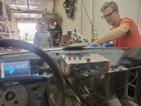
With stay at home orders progress has on the Baikal EV has slowed a bit. Considering the fact that Paul had to move his shop to a new location, we aren't doing too badly. Tyler mostly works alone fabricating and welding and we're all keeping our distance. I haven't been to the new shop yet but I've been working on software and my shifter setup from home.

newShop2.jpeg

Lots of room in the new shop

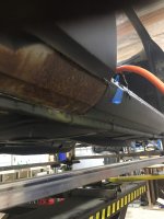
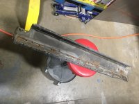
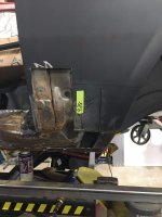
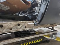
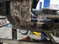
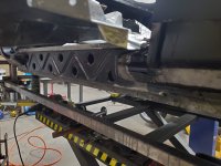
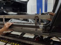
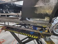
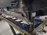
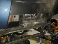
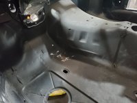
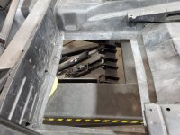
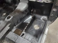
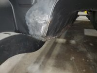
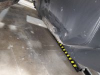
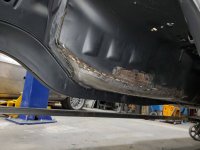
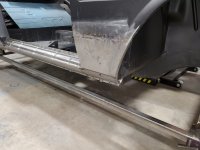
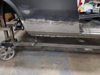
Last we "spoke" Tyler had finished the floors and we had installed the suspension. Before moving on to the battery box, we still had to fabricate the support for the rear subframe. Remember, in stock configuration, the rear subframe bolts to the diff, which is then mounted to the floor of the trunk via a rubber isolator mount. The prevents the subframe from rocking on its two main mounting locations at the rear corner of the rockers. Without the stock diff, we must come up with a new way of secure the rear suspension to the car. Paul pioneered this with his car and Tyler improved upon that design with mine. He fabricated a steel truss that he welded into the center of the subframe and extended forward into the prop shaft tunnel. He then reenforced the floor and attached a motor mount from a Chevy Suburban (< $20) to attach the truss to the car. Paul is using fancy Tesla electronic parking brake calipers but I am keeping the stock hand-operated parking brake so we had to work around the cable tubes on my car.

Truss1.jpg
Truss2.jpg


Truss3.jpg
Truss4.jpg


Truss5.jpg


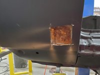
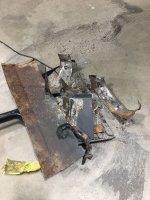
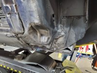
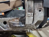
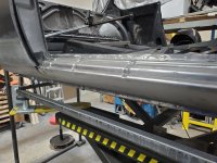
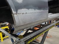
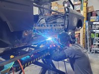
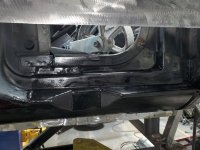
Next was to undo some crude handiwork from a PO in the kick panel area, where the supports had been butchered to make room for speakers.
kickpaneldamage2.jpg
kickpaneldamage.jpg
.

kickpanlerepair2.jpg
.
kickpanelrepair.jpg


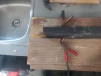
While Tyler was working his magic with metal, I was playing with CAD and 3D printing in an effort to adapt the factory automatic trans shifter to my needs. Again, Paul went a slightly different route, using a modern shifter from an Audi. I was hoping to keep the original shifter but realized that, without the detents in the auto trans itself, it was a floppy mess. I also need a way to convert the mechanical motion of the shifter to electrical signals I can send to the Drive Unit Controller of the Tesla motor. The original US auto shifter had gear indicator lights on the steering column so I figured I could repurpose the rotary switch bolted to the side of the old auto trans. If they could make it illuminate light bulbs then I could use it to send 12v signals to the Tesla. But I also needed detents to hold the handle in place so I devised a rotary unit comprised of three sandwiched plates with a round disc in between that had dimples on its edge. Then, a ball bearing and spring could push against the dimples, providing distinct stop points. Skateboard bearings held the D-shaft going through the disc. I'd then have to devise a linkage and lever system to make the shifter spin the shaft, similar to how the original gear selector shaft in the side of the auto trans operated.

RotaryCAD.png
RotaryPrototype.jpg


After numerous reprints to get the dimple depth right, it actually worked quite well as far as the detents were concerned. But when I tried to use it with the factory rotary light switch I realized that I didn't really understand how it worked. There are about 12 wires coming off that switch and a few hours with a multi-meter proved to me that there were no actual contacts in that switch. Instead, it appears to be a variable resistor (a potentiometer) with dead spots for the various gear positions? I eventually gave up and moved to plan B -- a linear, rather than rotary, system.

This one also took many reprints to get right. It operates somewhat like a player piano. There are 5 lever operated micro switches, one for each gear position (I will use "2" for max regen (or sport, TBD) mode but have no need for the 6th "1" position). "Domes" on a sliding plate, supported by 5 skateboard bearings, activate one switch at a time. the plate has dimples on the bottom edge, with the same ball bearing and spring mech from from rotary prototype provide detents. Linkage from the shifter arm attaches to the plate, making it slide in the housing, which will be attached to the trans tunnel.

LinearCAD.png
Mistakes.jpg


It took a while to figure out how far down the shift arm I needed to attach the linkage in order to get the proper "throw" to match the movement of the plate. So far, I've only mocked it up -- the spot-welded washer is not the permanent solution, and I was hesitant to lop off the rest of the arm until I was certain I've got it right -- but it works perfectly. Originally I thought I'd mill the entire thing out of aluminum but seeing it in action, I think that ABS is fine for everything except the sliding plate. You can see it work here: https://photos.app.goo.gl/841a9FsvRDovn5ZP7

LinearMech.jpg


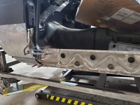
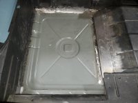
While messing around in CAD, I threw together a quick layout of how 10 Tesla batteries could fit in the engine compartment. Unlike Paul, I'm keeping stock steering and brakes so I had to work around the original ZF steering gearbox. This cost me room for two batteries (Paul fit 12 up front, 2 in the back -- I am putting 10 up front and 4 in the back). Tyler and Paul measured the actual car to see if my plan was feasible and it was, with one major flaw. When the 3/4" steel square tube of the box was added to the measurements, there wasn't enough room between the box and the brake mount. After some discussion, we decided to lop off the end of the steering tube, where the booster normally mounts, and cut into the factory battery tray (I'll only need a small gel cell for powering up electronics prior to energizing the Tesla system). This hurt but was necessary.

BatteriesCAD.png


How I'm going to relocate my brakes is still TBD but it is 90% likely that I will mount a small single line Wilwood master cylinder to the firewall. That will send hydraulic pressure to a remotely located small slave cylinder, which will move a rod analogous to the original brake pedal rod, into a hydroboost unit, and then to a master cylinder, either original or otherwise (need to figure out where to fit this remote setup and what to do about the two-line system to the original front calipers if I don't go with the original master).

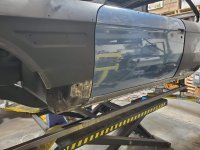
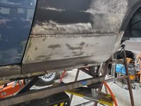
But that's work for a later day. In the meantime, the battery box is coming along nicely. Tyler made Paul's out of aluminum for weight savings but we decided to use steel for mine. It is heavier, but I have 110 pounds less batteries and it has been much faster to build and I figure battery density will improve so much in the coming years that this is just V1 anyway. I'll skin it in something (CF or alum sheet) later for weather protection.

batteryBox1.jpg
.

batteryBox2.jpg
 

dang

Administrator
Site Donor
Messages
4,247
Reaction score
3,262
Location
Rocklin, CA
Looks like you'll need to add some holes in your hood for post clearance. Maybe you can put little German flags on them. ;)
 

jefflit

Well-Known Member
Site Donor $
Messages
326
Reaction score
506
Location
Los Angeles, CA
Short update. The battery box is finished. Ten batteries slide in and the unit fits in the bay nicely. Tyler did some really great design whereby the longitudinal batteries tilt down slightly at the rear, lowering the height of the box, allowing the lateral battery on top at the rear to sit quite low. It easily clears the hood and all its bracing. We also have mounts on the box for attaching four eyehooks to lower the beast into the belly. The steel box weighs about 70 pounds, which is 30 more than Paul's aluminum version. Of course, I still have to skin it for weather protection but my plan for that is to lay up some sheets in carbon fiber so that shouldn't add much weight. Total weight is around 650 pounds. Paul has two more batteries in his box up front and the weight distribution has proven just fine. His car drives like a dream.

There is even room for the stock radiator (if I modify the lower hose outlet to clear). However, with the stock radiator there isn't much room between the radiator and the battery box for air to flow so I'm not sure if it will be the best choice. Paul is running a small motorcycle radiator in front of the core support. But he hasn't installed an A/C condenser yet either so room for a radiator, condenser, fan, and a small radiator to cool hydraulic fluid (brakes and steering) will make for a tight fit up front. My stock radiator with fittings for auto trans cooling lines would be great if I can modify all the inlets/outlets to work and can get enough airflow.

The battery box sits on the frame rails and is secured at the bottom to the factory motor mount locations. Up top, my plan is to secure the front portion of the box similar to how Paul did his -- to the core support but in back I'd like to tie the box to the top of the strut towers. I figured I could modify a three-piece strut tower brace by eliminating the middle portion and mounting the circular plates to the box. However, I haven't been able to locate a suitable donor brace. If anyone has a line on one I'd appreciate hearing from you. Otherwise, I'm going to have to design and cut my own circular plates.

20200529_141943.jpg


batteryBoxFilled1.jpg


batteryBoxFilled2.jpg


batteryBoxFilled3.jpg


On the coding front I've made some progress but I haven't spent as much time on it as I'd like. My PICAN2 CAN board decided to die and the micro SD card on the development pi also failed, so that slowed things down for a while. Finding a display to fit into the limited space of the tach hole has been tough. The current square display we are using is bulky and gave me a ton of trouble trying to get the rasppi to work with square resolution. I spent two nights playing with various HDMI settings and just couldn't get square output without stretching. We finally decided to try introducing a scaling device but along the way accidentally discovered that if I just leave the hdmi settings all at the defaults and set the hdmi_safe configuration flag to true, the raspberry pi figures it out on its own!

With that down, I just had to rotate the output 90 degrees because the display only fits into the cluster sideways. Still working on the final positioning so that it fits perfectly in the tach hole. There are both digital and analog (Tesla-like) modes for the tach hole, but the analog version is a work in progress (and Paul doesn't like it). I added a mode switch so the single codebase supports either small, square, rotated tach hole mode or normal rectangular speaker-hole touch-screen mode. I also added a little startup video to either mode. Now I need to integrate it with GPIO and a signal from the ignition switch and add a few more features. Small video here: https://photos.app.goo.gl/xmojZVR6WG1LiqhAA

Screen Shot 2020-06-21 at 8.55.30 AM.png
Screen Shot 2020-06-21 at 8.56.59 AM.png


Screen Shot 2020-06-21 at 8.57.33 AM.png
Screen Shot 2020-06-21 at 9.10.35 AM.png


Screen Shot 2020-06-21 at 8.57.59 AM.png
.
Screen Shot 2020-06-21 at 9.07.09 AM.png


20200529_142008.jpg


Screen Shot 2020-06-21 at 9.10.48 AM.png
 

Markos

Well-Known Member
Site Donor
Messages
13,369
Reaction score
7,502
Location
Seattle, WA
Rather than cutting your own custom strut plates, consider using a factory strut bearing on top of the fender.

0BDA0094-7AAA-441A-9ABC-865272F9FBD5.jpeg
 

Rex Kapriellian

Well-Known Member
Messages
951
Reaction score
416
Location
Long beach california
The Tesla parts should arrive in a couple weeks. In the meantime, Brett has cut out the trunk area in anticipation of the motor install (I'm using the smaller Tesla rear-drive unit, by the way). The goal is 294 HP and 200 miles of range. There are still many, many details (battery placement, P/S, P/B, A/C, cooling, etc., etc.) to figure out. I'll use this thread as the place for how all that plays out. It's sure to be a long road.View attachment 74368

In the meantime, I'm learning CAN Bus programming and trying to integrate the Tesla data with the factory BMW gauges. Details to follow.
By semi-popular demand here it is... my build thread! Those who read my IKEA Effect thread know that I'm somewhat ambivalent about making this public but there was some interest and I think the build is interesting. To make a long story(so far) short, I started on a B35 swap that has crept into a full-on rotisserie restoration with Tesla EV conversion.

I bought a "nice from 15 feet" 73 Baikal Blue USA Automatic coupe off eBay back in 2015. My wife and I drove it home from NorCal but the secondaries were stuck closed in the Webers and the trans wouldn't kick down. I spent a few years fixing little things and driving it. It was fine but there was some rust (spare tire, right rear floor, rocker rear corners) and it smoked a bit on deceleration so I decided to embark on a motor upgrade and undercarriage cleanup, without messing with paintwork yet. I'd save that for a full resto at a later date.

View attachment 74328
I hate to admit, but this is the *before* photo

ChrisHB put me in touch with sfDon and I started assembling all the bits for a M30B35 swap. I got most all the parts together from Don and took the car to the SoCal Vintage meet in November 2018 before driving it home and beginning disassembly for the heart transplant. I was thinking I'd get it done over the holiday break. One thing led to another (unexpected rust, a "while I'm in there" attitude, and a desire to "do it right") and before you knew it I had built a chassis dolly and sent it off for media blasting.

View attachment 74329
This is what "Scope Creep" looks like

Along the way, JetDexter started his CSE build thread. I'd always been interested in electrification of old cars. My daughter has a 64 Impala lowrider and I always thought a lowrider would make a great candidate for EV (they aren't driven far and they're already full of batteries for the hydros and they have huge trunks and the lighter upfront the better for 3-wheel motion) but the idea was too expensive and complex.

View attachment 74330
My daughter loves her 327 SBC and one lowrider in the family is enough, really.

But I went to visit Paul's shop and caught his enthusiasm. His CSE project made me think the conversion was feasible so, despite having accumulated the best of everything for a B35 swap, I decided to ride his coat tails. Result? Be on the lookup for a a lot of "Electrification Forces Sale" posts on the Parts board in the next few weeks. If you're in the market for a "best of everything" show quality, ceramic coated, zinc plated, etc, etc. B35, 5-speed, LSD driveline let me know. Feel free to ask Don about provenance.

At this point, the car is sitting next to Paul's and Tyler has started rust repair. Fortunately, there were no big surprises from blasting. A few pinholes in the roof at the back edge of the sunroof and a little bit of prior bodywork near the right front turn signal but otherwise nothing I didn't already know about.

View attachment 74331
Charlie: You were in a 4G inverted dive with a Mig 28?
Maverick: Yes, ma'am.
Charlie: At what range?
Maverick: Um, about two meters.
Goose: It was actually about one and a half I think. It was one and a half. I've got a great Polaroid of it, and he's right there, must be one and a half.
Maverick: It was a nice picture.
Goose: Thanks.
Charlie: Eh, lieutenant, what were you doing there?
Goose: Communicating.
Maverick: Communicating. Keeping up foreign relations. You know, giving him the bird?


View attachment 74332
The factory undercoat was tough to remove. Even media blasting just bounces off.


View attachment 74340
The exterior body panels were blasted with plastic bead so no heat, no warping.
View attachment 74333
After media blast with "dirty 30" grit. I had patched the right rear floor before giving in to professional help. I had also cut out part of the right front floor and opened up the rear rocker corners. Obviously, the spare wheel well was toast, but that just made the decision to go electric that much easier. Other than that, it really wasn't too bad.


View attachment 74334
Prior to sealing. Before someone gets all wiggy about the rotisserie bracket mounts, this is a US car so it has big braces welded in behind the bumper brackets, plus they welded in some braces to the trunk floor also. No coupes were harmed in this photo.


View attachment 74336
Other than the known spots, it really is quite solid.


View attachment 74337
The shock towers are perfect. No rebar and fiberglass here (that one's for you, Paul).


Just found this thread. I have always wanted to do an EV swap. This looks amazing!
 
Top