Wow, just amazing Jeff.
You are using an out of date browser. It may not display this or other websites correctly.
You should upgrade or use an alternative browser.
You should upgrade or use an alternative browser.
Blue EV build
- Thread starter jefflit
- Start date
-
- Tags
- restoration list
Awesome build! Please keep updating.
Thank you for that thorough and always fascinating update, Jeff!
More stupidity from yours truly...
I attempted to fill the brake system but made about three mistakes, all having to do with filling before fully thinking things through. I filled the master only to find the fluid gushing onto the floor. I forgot that I had removed the stop light switch from the Wilwood prop valve. Doh! Fortunately, I had already sourced the 1/8" NPT plug to replace it so I just had to scramble to install it. Of course, the car was in the air so I was on a ladder plugging the port with my finger while explaining to Brett where I had put the plug....
After that fiasco, the good news was there were no leaks in the new lines and the fluid was flowing nicely with just gravity. Tthe bad news was that I hadn't tightened any of the bleed screws when I rebuilt the calipers. Again, I scrambled. The rears were easy to close, as were the inner fronts. I hadn't really planned on bleeding the system immediately -- I was just going to let gravity do its job for a few days and then bleed when I got back to the shop again -- so I had not removed the wheels/tires. Trying to rush, I was able to close the outer bleeders in front via the slots in the wheels.
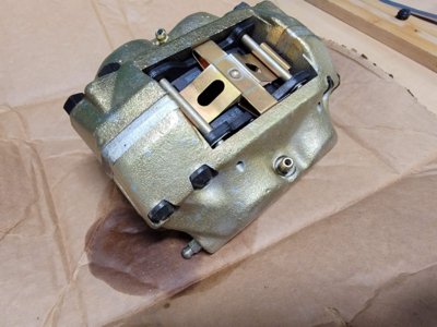
But there was still a leak from one front caliper. Rushing to judgement while trying to stop pissing on the floor, I assumed it must've been a problem with my caliper rebuild so my final task for the day was to finally pull the wheel and the caliper, looping a hose between the two hard lines to prevent further leakage. It wasn't until I got the caliper home that I realized there are actually 3 bleed screws in each front caliper. Doh! Well, at least it was an easy fix.
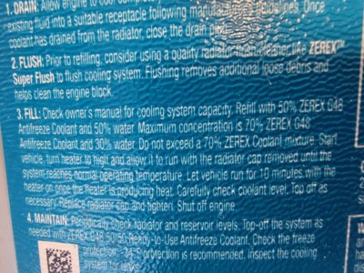
Bonehead move #4 is related to the battery coolant flow test. I ran another test Saturday to see if an overflow tank was really necessary. I rigged up the radiator, pump, and a single battery. This time I used water instead of coolant since, with just one battery, it would be easy enough to see the flow. The flow was actually pretty decent. Not the same as the input -- there is still significant restriction -- but plenty good enough. Promising. It wasn't until later, when thinking about the difference between the two tests, that I realized the one major difference. Coolant vs water. In my first test I used straight G48 coolant (not the pre-diluted stuff) but it is supposed to be diluted 50:50 with water. Doh! G48 I'm certain that the viscosity difference between straight and diluted will explain the reduced flow.
I need to slow down and make sure I don't pull any of these stunts when working with 300+ volts...
I attempted to fill the brake system but made about three mistakes, all having to do with filling before fully thinking things through. I filled the master only to find the fluid gushing onto the floor. I forgot that I had removed the stop light switch from the Wilwood prop valve. Doh! Fortunately, I had already sourced the 1/8" NPT plug to replace it so I just had to scramble to install it. Of course, the car was in the air so I was on a ladder plugging the port with my finger while explaining to Brett where I had put the plug....
After that fiasco, the good news was there were no leaks in the new lines and the fluid was flowing nicely with just gravity. Tthe bad news was that I hadn't tightened any of the bleed screws when I rebuilt the calipers. Again, I scrambled. The rears were easy to close, as were the inner fronts. I hadn't really planned on bleeding the system immediately -- I was just going to let gravity do its job for a few days and then bleed when I got back to the shop again -- so I had not removed the wheels/tires. Trying to rush, I was able to close the outer bleeders in front via the slots in the wheels.
But there was still a leak from one front caliper. Rushing to judgement while trying to stop pissing on the floor, I assumed it must've been a problem with my caliper rebuild so my final task for the day was to finally pull the wheel and the caliper, looping a hose between the two hard lines to prevent further leakage. It wasn't until I got the caliper home that I realized there are actually 3 bleed screws in each front caliper. Doh! Well, at least it was an easy fix.
Bonehead move #4 is related to the battery coolant flow test. I ran another test Saturday to see if an overflow tank was really necessary. I rigged up the radiator, pump, and a single battery. This time I used water instead of coolant since, with just one battery, it would be easy enough to see the flow. The flow was actually pretty decent. Not the same as the input -- there is still significant restriction -- but plenty good enough. Promising. It wasn't until later, when thinking about the difference between the two tests, that I realized the one major difference. Coolant vs water. In my first test I used straight G48 coolant (not the pre-diluted stuff) but it is supposed to be diluted 50:50 with water. Doh! G48 I'm certain that the viscosity difference between straight and diluted will explain the reduced flow.
I need to slow down and make sure I don't pull any of these stunts when working with 300+ volts...
Attachments
Slip happens. The original goal was to drive it by the end of September. That came and went. Rewiring a car is surprisingly time consuming.
I figured what I needed was a commitment device so I signed up for the SoCal Vintage meet and spent my $25 in reg fees. OK, it wasn't a big commitment but I actually took almost a week off work in attempt to drive the car onto the grass in Van Nuys last Saturday. Needless to say, I didn't make it. Thursday night/Friday in the ER with a family member didn't help but I don't think that was the deciding factor. I'm sorry to have missed seeing you all -- I spent Saturday working on the car instead. I'm SOOO close but not quite there yet.
The details are in my blog at https://bmwcse.blogspot.com/
Talk to you again after Thanksgiving?
I hope your family member is ok.
Nice vid for sure. Amazing how much time we spend going down to the floor and then back up and then back down and…
Nice vid for sure. Amazing how much time we spend going down to the floor and then back up and then back down and…
I told you I was close. First test drive was today.
Congrats! Now before your next test drive fix your steering wheel alignment! 
That has to be an amazing feeling of satisfaction!!
Such a journey!! Wow! Keep it up!!
Such a journey!! Wow! Keep it up!!
alexbeatle
New Member
What an amazing build!
Would you be able to share some info? I'm planning my own EV conversion project.
Would you be able to share some info? I'm planning my own EV conversion project.
- Which radiators and pumps you've used?
- Which condenser and the a/c compressor you've used?
- Did you put in a battery heater?
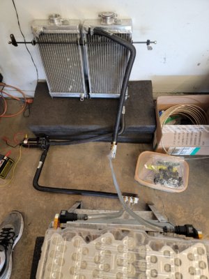
The radiators are Champion radiators designed for 125cc shifter karts. Paul used a single Kawasaki motorcycle radiator but was only cooling the inverter/motor/dc-dc/obc, not the batteries. I first purchased a dragster radiator with nice threaded AN bungs but it didn't fit in the core support opening so I went with the kart units. They have 5/8" nipples, which matches the nipples on the Tesla drive unit and the OBC/DC-DC.
I'm actually happy now to have separate loops for the batteries and other units, as the desired/critical temps are quite different. The batteries want to live at 80-100F while the motor/inverter/PCB runs at 130F so I don't have the motor heating up the batteries. I have two separate temp sensors controlling when the fan comes on, each set at different thresholds. Tesla does this with valves, which is also possible.
The pumps are Bosch 0 392 022 002 , designed for liquid/air intercoolers. 1200 liters per hour (5.2 gallons per minute). OEM quality. They draw about 4 amps.
The A/C condenser is a generic parallel flow unit. 16" (406 mm) X 20" (508 mm) X 0.709" (18 mm). That's about as large as you can fit in there and still get to the hose fittings.
I'm using the electric A/C compressor from Tesla model S (2013 / 2014), part number 6007380-00-D. It is actually made by Denso (ES34C) and used on some Mercedes as well, I believe. It is 300+ VDC, PWM controlled so you'll need something that can generate the PWM signal for speed control. I will most likely use an Arduino but I haven't finished all my HVAC yet.
While I do have a high voltage heater for the cabin, I'm not doing any battery heating. I live in Southern California and this is a "fun" car so I can ignore a lot of extreme weather concerns, especially cold. As you probably know, Tesla has some very complex temperature management, with both heating and cooling (via A/C). Paul drove his car for a year without any battery heating or cooling and was fine so, for me, a lot of this is just to have flow for consistent temps.
amazing..
alexbeatle
New Member
Nice! Thanks for filling the gaps for me.The radiators are Champion radiators designed for 125cc shifter karts. Paul used a single Kawasaki motorcycle radiator but was only cooling the inverter/motor/dc-dc/obc, not the batteries. I first purchased a dragster radiator with nice threaded AN bungs but it didn't fit in the core support opening so I went with the kart units. They have 5/8" nipples, which matches the nipples on the Tesla drive unit and the OBC/DC-DC.
I'm actually happy now to have separate loops for the batteries and other units, as the desired/critical temps are quite different. The batteries want to live at 80-100F while the motor/inverter/PCB runs at 130F so I don't have the motor heating up the batteries. I have two separate temp sensors controlling when the fan comes on, each set at different thresholds. Tesla does this with valves, which is also possible.
The pumps are Bosch 0 392 022 002 , designed for liquid/air intercoolers. 1200 liters per hour (5.2 gallons per minute). OEM quality. They draw about 4 amps.
The A/C condenser is a generic parallel flow unit. 16" (406 mm) X 20" (508 mm) X 0.709" (18 mm). That's about as large as you can fit in there and still get to the hose fittings.
I'm using the electric A/C compressor from Tesla model S (2013 / 2014), part number 6007380-00-D. It is actually made by Denso (ES34C) and used on some Mercedes as well, I believe. It is 300+ VDC, PWM controlled so you'll need something that can generate the PWM signal for speed control. I will most likely use an Arduino but I haven't finished all my HVAC yet.
While I do have a high voltage heater for the cabin, I'm not doing any battery heating. I live in Southern California and this is a "fun" car so I can ignore a lot of extreme weather concerns, especially cold. As you probably know, Tesla has some very complex temperature management, with both heating and cooling (via A/C). Paul drove his car for a year without any battery heating or cooling and was fine so, for me, a lot of this is just to have flow for consistent temps.
View attachment 130998
Do you find batteries kick a lot of cooling during the charging sessions? Are you using only level2 charging or rapid charging, as well?
To be clear, I haven't charged my car yet. That'll happen this week though -- I just programmed the BMS this weekend but I didn't have an EVSC at the shop. My pack is currently at 46.5% state of charge but I'll bring my EVSC to the shop this week to charge it up completely.
That said, Paul drove his car for a year with no battery cooling at all and obviously charged it many times. No, we do not do fast DC charging, just 30-40 amp level 2 with a 6.6kw charger. This gives about 30-35 miles of range per hour of charge and does not generate much heat in the batteries.


That said, Paul drove his car for a year with no battery cooling at all and obviously charged it many times. No, we do not do fast DC charging, just 30-40 amp level 2 with a 6.6kw charger. This gives about 30-35 miles of range per hour of charge and does not generate much heat in the batteries.
alexbeatle
New Member
Thank you so much for the info. You answered a lot of questions which I couldn't find straight answers to.
One more thing, please.
I'm currently mounting my ibooster. I will use the same proportional valve and will also add a residual pressure valve (due to drum brakes at the rear) from Wilwood.
All these, plus my brake lines have different flares styles.
I see you've done amazingly with your setup.
Could you please share where do you source all different fittings and reducers? Ex. I booster has 6mm brake line with M12-1 double flare nuts, but the proportional valve uses 3/16 lines (I believe same as 4.75mm) brake lines with 3/8"-24 double flare nuts.
Yes, we end up with a crazy mix of metric and SAE. All the old ATE stuff (calipers, hoses) are DIN bubble flare but the WIlwood stuff (prop valve) is all 3/8-24 in. inverted double flare while the Bosch/Tesla iBooster master is a super-odd 12mm fitting but with an inverted flare not a DIN bubble. Also, the iBooster master lines are large (I forget exact size but approx 1/4") while the Wilwood prop value 3/8" fittings are designed for 3/16" lines. I cut the pipe off the original Telsa 12mm fittings and flared new lines to the old nuts. Then I soldered those lines to some AN fittings that I was able to connect to the smaller lines to the prop valve. From there, it is all pretty straight-forward with 3/16" line use 3/8" inverted flares on the prop valve side and DIN bubble flares to the hoses, except for the fact that I needed to Y the lines from one to two for the front hoses. I did that with AN fittings.


While writing about brakes, and continuing the habit of airing the mistakes...
I had a great, nice, hard pedal after bleeding the brakes but on the test drive I pushed the pedal super hard as a test and it went to the floor but didn't come back up. This wasn't super concerning since it was a slow speed test drive with lots of regen braking and still some stopping from the pedal but it was confusing.
When I got back to the shop, Brett pulled super hard upwards on the pedal and it returned to the correct position. WTF? Well, I had assumed that the pedal was securely affixed to the pivot tube and that all rotation occurred with the entire assembling rotating around the bushings in the pivot tube. Makes logical sense, right?
Well, I'm here to tell you that the pedal's crush fit to the tube is not entirely secure. It keeps the pedal from drifting side-to-side but does not prevent it, under large load, from rotating around the pivot. Normally, that isn't a problem since the pedal is directly acting upon the rod to the master so where it rotates is irrelevant but since I welded the brake and clutch pivots together so that I could transfer the motion leftwards to the clutch pedal in order to get necessary clearance for my battery box this suddenly becomes critical.
Nothing a quick TIG welding couldn't fix and I'm glad I discovered it on the slow test drive but a lesson none-the-less. Pedal is hard as a rock now.
I'm basically calling this EV conversion project finished.
I'm driving the car (albeit without windshield, doors, etc). I drove it in and out of an EV show two weeks ago. It drives super smooth, brakes perfectly, steers perfectly, and is insanely quick (really lights up the tires). Maybe I'll make the de rigueur burn out video soon. On Saturday I got the BMS all configured and charged the car for the first time. The pumps came on as expected and everything worked as planned. I'm super pleased.
There are some things still to do: finish HVAC (still waiting on the electric heating coil), some 12v wiring, finish programming the analog gauges and install the touch screen somewhere, etc. And there is still some metal finishing to do.
Then there's the small issue of restoration. I'm not really looking forward to disassembling it all for paint. I'll be reaching out for help on a number of the fiddly items when that time comes I'm sure.


Things have gotten dusty in the time I've been working on the EV stuff but it should all clean up again when removed.


I'm driving the car (albeit without windshield, doors, etc). I drove it in and out of an EV show two weeks ago. It drives super smooth, brakes perfectly, steers perfectly, and is insanely quick (really lights up the tires). Maybe I'll make the de rigueur burn out video soon. On Saturday I got the BMS all configured and charged the car for the first time. The pumps came on as expected and everything worked as planned. I'm super pleased.
There are some things still to do: finish HVAC (still waiting on the electric heating coil), some 12v wiring, finish programming the analog gauges and install the touch screen somewhere, etc. And there is still some metal finishing to do.
Then there's the small issue of restoration. I'm not really looking forward to disassembling it all for paint. I'll be reaching out for help on a number of the fiddly items when that time comes I'm sure.
Things have gotten dusty in the time I've been working on the EV stuff but it should all clean up again when removed.
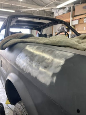
With the EV conversion done, the last couple months have all been dominated by metal work. I'm trying to get the body as perfect as possible in steel so there has been a lot of tedious metal finishing.

On top of the small dents, etc., there has been a lot of custom work as well to clean up some things. Of course, I filled the US side marker holes and the washer jet holes (I'm never going to squirt fluid onto my windshield and don't have room for the bottle anyway). But I've taken it a bit further. I realize this isn't everyone's cup of tea but there are a few areas on the coupes that I felt could be improved so I went for it.
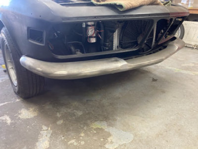
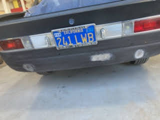
First was the bumpers. Mine was a US spec car with the bumpers pushed way out and ugly so tucking them in to Euro spec was an obvious choice. Personally, I'm not a fan of the rubber strips or over riders/under riders. I don't drive by Braille and am of the opinion that the cars were originally designed for the 2000 CS all chrome style bumpers. The rear is easy -- just buy a 2000 CS rear bumper. Problem solved. The front, not so much.
As already mentioned in the CSL Bumper thread, I like the shape of the CSL front bumper, only I want mine in chrome, not black fiberglass. Thus began the non-trivial exercise of modifying an e9 3-piece bumper into a single rubber-less unit with no visible attachment hardware. Welding on steel that had previously been copper plated and still has some copper in the pores is difficult. Everything has to be perfectly finished in steel (no lead or fillers) to support proper chrome plating when done. It is all done now, except for the chrome and I'm very pleased with the result. Of course, I tucked it in as tight as possible while at it.


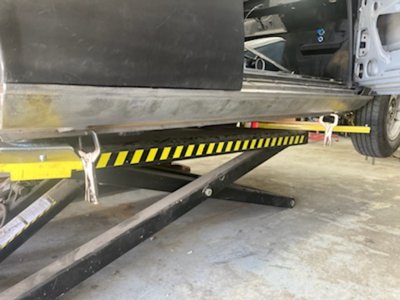
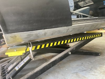
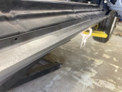
One reason I haven't sent it off for chrome yet is the rocker trim. I'm not a fan of the stone guard finish or the black rocker panels, or the big rubber trim. I think the black raises the visual height of the car and the rubber is too bulky now that I have clean rubber-free bumpers. My trim found a new home with @HB Chris and filling the trim holes was easy enough but I hadn't thought through my original plan for body colored rocker covers well enough.
When the covers were mounted to the car I realized that the factory fit was a bit, shall we say, vague? There are inconsistencies where the top edge of the cover comes somewhat close to the reveal line on the fenders and quarters but the gap is big. The factory hid this with rubber, which is OK when the panel is black but not acceptable if everything is body color. Also, the top edge of the cover has just a very small lip that is visible when the rubber is removed. All in all, it just wasn't clean.

My solution is a simple piece of metal trim that runs the entire length of the rocker cover and gives a straight line along the fender and quarter reveals and the lower edge of the door. The trim has a convex curve to it and wraps up into the door sill where the edge is covered by the factory bright sill cover. This trim bolts to the rocker cover. Again, a lot of work went into this and it still needs to be chrome plated but I really like the result. It doesn't exactly match the belt-line trim but it's similar.


Keep in mind, many places where I say "I" I actually mean Tyler as I've been relying upon his metal working skills to accomplish all this. While he does that, I've been working on the other CSE and building and programming circuits for HVAC, shifting, battery management, gauges, etc. I'm learning to program Local Interconnect Network (LIN) devices, a standard I had been previously unaware of but was created by BMW, Volkswagen, Audi, Volvo, and Mercedes-Benz. It is a single wire, serial network protocol that supports communications up to 19.2 Kbit/s at a bus length of 40 meters for controlling devices where a traditional CAN Bus is considered too complicated. While most of my systems use CAN, I'm now working with a high voltage cabin water heater from a VW that uses LIN. Fun stuff.
On top of the small dents, etc., there has been a lot of custom work as well to clean up some things. Of course, I filled the US side marker holes and the washer jet holes (I'm never going to squirt fluid onto my windshield and don't have room for the bottle anyway). But I've taken it a bit further. I realize this isn't everyone's cup of tea but there are a few areas on the coupes that I felt could be improved so I went for it.
First was the bumpers. Mine was a US spec car with the bumpers pushed way out and ugly so tucking them in to Euro spec was an obvious choice. Personally, I'm not a fan of the rubber strips or over riders/under riders. I don't drive by Braille and am of the opinion that the cars were originally designed for the 2000 CS all chrome style bumpers. The rear is easy -- just buy a 2000 CS rear bumper. Problem solved. The front, not so much.
As already mentioned in the CSL Bumper thread, I like the shape of the CSL front bumper, only I want mine in chrome, not black fiberglass. Thus began the non-trivial exercise of modifying an e9 3-piece bumper into a single rubber-less unit with no visible attachment hardware. Welding on steel that had previously been copper plated and still has some copper in the pores is difficult. Everything has to be perfectly finished in steel (no lead or fillers) to support proper chrome plating when done. It is all done now, except for the chrome and I'm very pleased with the result. Of course, I tucked it in as tight as possible while at it.
One reason I haven't sent it off for chrome yet is the rocker trim. I'm not a fan of the stone guard finish or the black rocker panels, or the big rubber trim. I think the black raises the visual height of the car and the rubber is too bulky now that I have clean rubber-free bumpers. My trim found a new home with @HB Chris and filling the trim holes was easy enough but I hadn't thought through my original plan for body colored rocker covers well enough.
When the covers were mounted to the car I realized that the factory fit was a bit, shall we say, vague? There are inconsistencies where the top edge of the cover comes somewhat close to the reveal line on the fenders and quarters but the gap is big. The factory hid this with rubber, which is OK when the panel is black but not acceptable if everything is body color. Also, the top edge of the cover has just a very small lip that is visible when the rubber is removed. All in all, it just wasn't clean.
My solution is a simple piece of metal trim that runs the entire length of the rocker cover and gives a straight line along the fender and quarter reveals and the lower edge of the door. The trim has a convex curve to it and wraps up into the door sill where the edge is covered by the factory bright sill cover. This trim bolts to the rocker cover. Again, a lot of work went into this and it still needs to be chrome plated but I really like the result. It doesn't exactly match the belt-line trim but it's similar.
Keep in mind, many places where I say "I" I actually mean Tyler as I've been relying upon his metal working skills to accomplish all this. While he does that, I've been working on the other CSE and building and programming circuits for HVAC, shifting, battery management, gauges, etc. I'm learning to program Local Interconnect Network (LIN) devices, a standard I had been previously unaware of but was created by BMW, Volkswagen, Audi, Volvo, and Mercedes-Benz. It is a single wire, serial network protocol that supports communications up to 19.2 Kbit/s at a bus length of 40 meters for controlling devices where a traditional CAN Bus is considered too complicated. While most of my systems use CAN, I'm now working with a high voltage cabin water heater from a VW that uses LIN. Fun stuff.
Attachments
-
 fenderDent.jpeg23.9 KB · Views: 270
 -
 frontBumper.jpeg38.2 KB · Views: 302
 -
 frontBumperEnd.jpeg27 KB · Views: 252
 -
 lowerRearValance.jpeg38.1 KB · Views: 267
 -
 rockerTrimProfile.jpeg24.5 KB · Views: 240
 -
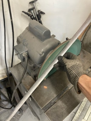 rockerTrimSanding.jpeg31.4 KB · Views: 243
 -
 rockerTrim1.jpeg50 KB · Views: 270
 -
 rockerTrim2.jpeg49.8 KB · Views: 257
 -
 rockerTrimDoorSill2.jpeg40.1 KB · Views: 258
Very impressive work, Jeff! I really like what you’ve done with the front bumper. I have shortened mine on the sides so I could tuck it in closer as well.