Hi Team. I set out this year to find a replacement evaporator for the AC systems in our E9s and E3s (and E12s and E21s).
I found one (originally made for a 2007 Land Cruiser). It fits in the original box pretty well and it’s in my car working now. I’ll show you how I did it and then update you at some point in the near future as to whether there’s any advantage to it over the original parts. This is a work in progress and you are joining me in the experiment!
I want to emphasize that many members on this board have made their AC systems work pretty well using the original BMW parts and that if you are in need of better cooling in your car start with the basics by making sure your system is charged with the correct amount of oil and refrigerant; making sure that you’ve cleaned the bees out of your condenser; inspecting your switches and wires; checking if the seals are still there on the little flappy doors inside your heater box; and seeing to other correctable things.
On the outset, I wanted to find an evaporator upgrade method made from cheap, commercially available, and reliable parts that could be shared as a DIY guide that anyone could follow. How’d this turn out?
Is it an upgrade?: TBD
Is it cheap?: Pretty affordable I guess. See the spreadsheet below.
Is it reliable?: I already feel better knowing that the connections have o-rings, not copper washers.
Are the parts commercially available: Most yes, some no.
Can anyone do this?: Yes, except for a few parts which are hard to fabricate. Read on.
Here is the stock evaporator box with its big tube-and-fin evaporator.

Here’s the old evaporator and associated plumbing.

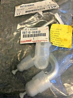
Here are the new evaporator, thermal expansion valve (“TXV”), and associated plumbing:


I modeled all of these parts to make selecting an evaporator from the Internet easier. You can see here that this new evaporator isn’t quite as tall as the old one but it fits in the box snugly against the blower cavity despite not being quite as tall as the old one.

Below are all the parts needed for this conversion as well as a source for them (in the spreadsheet). This assumes you have an original AC box with a working blower assembly and that you’re willing to modify the box.


Here is the kit assembled and in the box (top view):

Thoughts and reflections:
I’m pleased! It’s been cloudy but I got a sunny day today finally. I got a chance to run the system starting with an interior temperature of 107º. I was measuring temperature drops (measurement of air going in minus air coming back out) of as much as 35º as the cabin cooled down. I’m going to keep tweaking some things to see if I can get more cooling.
I didn’t make any modifications to the blower even though it is probably the biggest limitation in this system. I’ve determined that the blower (with whichever evaporator is in the box) makes about 190 cubic feet per minute of airflow. If I’d found a way to switch the blower and the evaporator at the same time in this experiment there’d be know way to know which made the bigger difference.
I wanted this to be made completely from parts anyone could source. The 3D printed stuff I’m kind of excusing here since there are probably dozens of ways to secure an evaporator in a plastic box and 3D printing was just the easy way for me. Also, I can share those files with anyone who wants them.
As far as the fit of the new system, it was kind of a bummer that the TXV interfered with the back of the box since it was almost a perfect match. Have a look at this cross section:

View from the bottom of the valve and the box cutout:

A window shaped like this needs to be cut out from the box. Aside from that, the only other modifications to the box is a few screw holes.

The blue plate (part D4 on the illustration) is a shell that makes a little more clearance around the TXV (particularly at the bottom) and also collects dripping condensate and returns it to the bottom of the box using gravity. I have it installed pressed against a foam seal and I’ll be checking it periodically this summer to make sure it doesn’t leak. It could also be glued in with silicone.
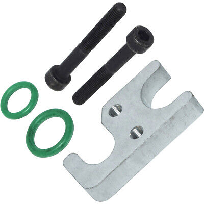
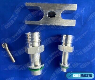
The real missing link I couldn’t find on any website was an adaptor from that particular TXV to an O-ring-stye connector and a clamp to squeeze them on. I’m referring to parts C3, C4, and F on the diagram. I made the adaptors on my little lathe and brazed them to tubing.

This was my first time brazing. It seems to have worked well but I know this option isn’t easily available to everyone at home.
Presumably I or someone more experienced than me could make this assembly into a kit if the DIY route is too confusing. Also, I took all the pictures needed for a full "how-to" guide. But I think anyone with enough ability to take their box out of their car and / or charge up an A/C system should be able to assemble this.
I have enough parts for another prototype if someone with time on their hands wants to reimburse me for just the parts and postage. All I’d ask is that you’d be able to compare this system with the previous one in your car and report back for everyone’s benefit.
Anyway, it can now be said that someone has used a non-original evaporator in an E9. I’ll post a critique of the function soon. So far so good. Thanks for following along!
I found one (originally made for a 2007 Land Cruiser). It fits in the original box pretty well and it’s in my car working now. I’ll show you how I did it and then update you at some point in the near future as to whether there’s any advantage to it over the original parts. This is a work in progress and you are joining me in the experiment!
I want to emphasize that many members on this board have made their AC systems work pretty well using the original BMW parts and that if you are in need of better cooling in your car start with the basics by making sure your system is charged with the correct amount of oil and refrigerant; making sure that you’ve cleaned the bees out of your condenser; inspecting your switches and wires; checking if the seals are still there on the little flappy doors inside your heater box; and seeing to other correctable things.
On the outset, I wanted to find an evaporator upgrade method made from cheap, commercially available, and reliable parts that could be shared as a DIY guide that anyone could follow. How’d this turn out?
Is it an upgrade?: TBD
Is it cheap?: Pretty affordable I guess. See the spreadsheet below.
Is it reliable?: I already feel better knowing that the connections have o-rings, not copper washers.
Are the parts commercially available: Most yes, some no.
Can anyone do this?: Yes, except for a few parts which are hard to fabricate. Read on.
Here is the stock evaporator box with its big tube-and-fin evaporator.
Here’s the old evaporator and associated plumbing.
Here are the new evaporator, thermal expansion valve (“TXV”), and associated plumbing:
I modeled all of these parts to make selecting an evaporator from the Internet easier. You can see here that this new evaporator isn’t quite as tall as the old one but it fits in the box snugly against the blower cavity despite not being quite as tall as the old one.
Below are all the parts needed for this conversion as well as a source for them (in the spreadsheet). This assumes you have an original AC box with a working blower assembly and that you’re willing to modify the box.
Here is the kit assembled and in the box (top view):
Thoughts and reflections:
I’m pleased! It’s been cloudy but I got a sunny day today finally. I got a chance to run the system starting with an interior temperature of 107º. I was measuring temperature drops (measurement of air going in minus air coming back out) of as much as 35º as the cabin cooled down. I’m going to keep tweaking some things to see if I can get more cooling.
I didn’t make any modifications to the blower even though it is probably the biggest limitation in this system. I’ve determined that the blower (with whichever evaporator is in the box) makes about 190 cubic feet per minute of airflow. If I’d found a way to switch the blower and the evaporator at the same time in this experiment there’d be know way to know which made the bigger difference.
I wanted this to be made completely from parts anyone could source. The 3D printed stuff I’m kind of excusing here since there are probably dozens of ways to secure an evaporator in a plastic box and 3D printing was just the easy way for me. Also, I can share those files with anyone who wants them.
As far as the fit of the new system, it was kind of a bummer that the TXV interfered with the back of the box since it was almost a perfect match. Have a look at this cross section:
View from the bottom of the valve and the box cutout:
A window shaped like this needs to be cut out from the box. Aside from that, the only other modifications to the box is a few screw holes.
The blue plate (part D4 on the illustration) is a shell that makes a little more clearance around the TXV (particularly at the bottom) and also collects dripping condensate and returns it to the bottom of the box using gravity. I have it installed pressed against a foam seal and I’ll be checking it periodically this summer to make sure it doesn’t leak. It could also be glued in with silicone.
The real missing link I couldn’t find on any website was an adaptor from that particular TXV to an O-ring-stye connector and a clamp to squeeze them on. I’m referring to parts C3, C4, and F on the diagram. I made the adaptors on my little lathe and brazed them to tubing.
This was my first time brazing. It seems to have worked well but I know this option isn’t easily available to everyone at home.
Presumably I or someone more experienced than me could make this assembly into a kit if the DIY route is too confusing. Also, I took all the pictures needed for a full "how-to" guide. But I think anyone with enough ability to take their box out of their car and / or charge up an A/C system should be able to assemble this.
I have enough parts for another prototype if someone with time on their hands wants to reimburse me for just the parts and postage. All I’d ask is that you’d be able to compare this system with the previous one in your car and report back for everyone’s benefit.
Anyway, it can now be said that someone has used a non-original evaporator in an E9. I’ll post a critique of the function soon. So far so good. Thanks for following along!
Last edited by a moderator:

")