Fixing that little rust spot...

eriknetherlands

Moderator
Site Donor
Messages
2,697
Reaction score
1,929
Location
Netherlands, Eindhoven area
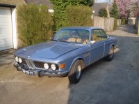
You know, while you are at it.....
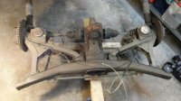
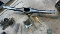
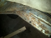
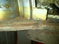
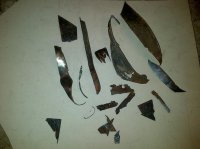
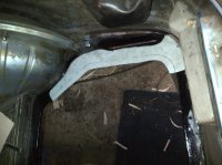
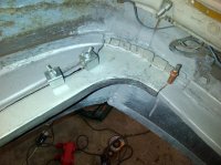
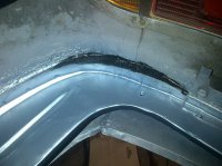
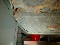
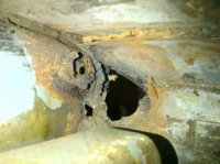
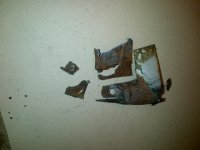
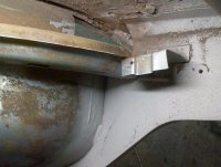
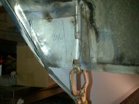
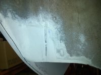
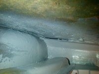
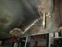
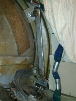
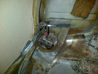
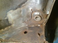
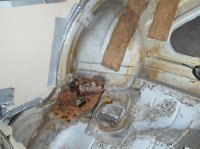
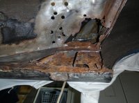
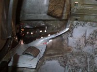
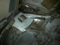
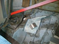
I had enough corrosion in the sill corners and the rear subframe mounting points of the thurst rod to think; let's do this over the coming winter.

So "while you are at", is getting difficult on me. I'd like to say: "well this can wait for another time". But I can't. It feels too much like cutting corners.

It may have to do with the fact that my hex keys are neatly ordered next too each other, spooning oneanother. branded side up. cleaned after use.

the "coming winter" was the one in 2012....

Let's share some good and ugly.
I am a car novice. A degree in engineering, yes, but never worked on anything bigger then a '69 moped (German as well by the way!) Did work in vehicle engineering for 7 years (Volvo, Mitsubishi & Mercedes) but mainly foccused on interior components at that time.

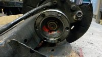
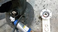
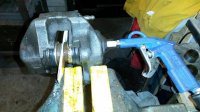
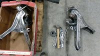
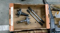
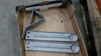
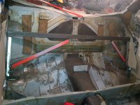
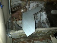
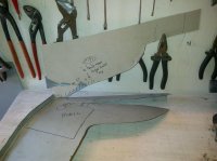
Now i'm moving on into the mechanicals....

I am very, very open to comments. When you spot something strange/stupid; let me know.
Here to learn what i want and share what I can.

I am going to throw in some stuff of the past 3 years, togther with questions as they come up. Don't try to find any chronological traces, i am already lost in the pile of pictures on my laptop...
 

Attachments

  • 2009-when i bought it.jpg
    2009-when i bought it.jpg
    334.4 KB · Views: 399
Last edited:

eriknetherlands

Moderator
Site Donor
Messages
2,697
Reaction score
1,929
Location
Netherlands, Eindhoven area
so a pic of how he was before we begun. Helps to keep focussed.

well, it actually is a picture of when I purchased the car. Hood is a bit skewed, was fixed by readjusting the bolt positions on the innerfenders.

I actually have a picture up in the garage as well as trigger to keep me going. Really helps sometimes when certain nuts and bolts are not listening to my advise.
 

Attachments

  • P4130255-1.jpg
    P4130255-1.jpg
    55.3 KB · Views: 1,652

eriknetherlands

Moderator
Site Donor
Messages
2,697
Reaction score
1,929
Location
Netherlands, Eindhoven area
First some small body work as practice

boot / trunk area. Rust spots around the fuel tank opening.
 

Attachments

  • IMG-20120218-00068.jpg
    IMG-20120218-00068.jpg
    89.2 KB · Views: 876
  • IMG-20120218-00072.jpg
    IMG-20120218-00072.jpg
    92.8 KB · Views: 825
  • IMG-20120423-00312.jpg
    IMG-20120423-00312.jpg
    98 KB · Views: 796
  • IMG-20120324-00191.jpg
    IMG-20120324-00191.jpg
    74 KB · Views: 795
  • IMG-20120406-00277.jpg
    IMG-20120406-00277.jpg
    63.3 KB · Views: 789
  • IMG-20120509-00352.jpg
    IMG-20120509-00352.jpg
    87.6 KB · Views: 801

eriknetherlands

Moderator
Site Donor
Messages
2,697
Reaction score
1,929
Location
Netherlands, Eindhoven area
The drain hole.... that got bigger by itself.

I tried to weld it so that it would be at least visible as i could. So i copied the flange that joins thie inner and outer 'shells' that make up the wheel arch.

2 patches were welded in; one section is the wheel arch, the other the boot floor.
 

Attachments

  • IMG-20120316-00113.jpg
    IMG-20120316-00113.jpg
    88.8 KB · Views: 833
  • IMG-20120404-00270.jpg
    IMG-20120404-00270.jpg
    90.3 KB · Views: 798
  • IMG-20120426-00333.jpg
    IMG-20120426-00333.jpg
    99.7 KB · Views: 745
  • IMG-20120423-00325.jpg
    IMG-20120423-00325.jpg
    97.2 KB · Views: 758
  • IMG-20120430-00338.jpg
    IMG-20120430-00338.jpg
    92.6 KB · Views: 769
  • IMG-20120508-00340.jpg
    IMG-20120508-00340.jpg
    92.4 KB · Views: 743
  • IMG-20120508-00344.jpg
    IMG-20120508-00344.jpg
    94.4 KB · Views: 760

eriknetherlands

Moderator
Site Donor
Messages
2,697
Reaction score
1,929
Location
Netherlands, Eindhoven area
Dug into the really bad stuff

I only have a small garage, so I can only work on one side of the car. It does have a lift, although it only goes up about 4 feet.

But that's enough to get around.

So begun peeling near the trust rod mounting points and near the big bolt that hold the rear axle bushing. Lot's of rust, creeping into every corner like a spiders web.

And it caught me.
 
Last edited:

eriknetherlands

Moderator
Site Donor
Messages
2,697
Reaction score
1,929
Location
Netherlands, Eindhoven area
pics

Do not think the colors on your monitor have shifted towards brown.
Its the same on my screen.

I welded a piece of tube onto the reinforcement plate, and rigged a frame to be able to position it in space to keep the alignment of the rear axle subframe mounting points correct.
 

Attachments

  • IMG-20120316-00109.jpg
    IMG-20120316-00109.jpg
    72.9 KB · Views: 838
  • IMG-20120320-00156.jpg
    IMG-20120320-00156.jpg
    79.6 KB · Views: 792
  • IMG-20120319-00143.jpg
    IMG-20120319-00143.jpg
    62.1 KB · Views: 773
  • IMG-20120318-00130.jpg
    IMG-20120318-00130.jpg
    78.6 KB · Views: 815
  • IMG-20120320-00169.jpg
    IMG-20120320-00169.jpg
    65.7 KB · Views: 775
  • P5110075.jpg
    P5110075.jpg
    63.8 KB · Views: 753
  • P5110077.jpg
    P5110077.jpg
    63.5 KB · Views: 810
Last edited:

eriknetherlands

Moderator
Site Donor
Messages
2,697
Reaction score
1,929
Location
Netherlands, Eindhoven area
Metal bashing

So, going at it. i tried to make a piece as large as i could in one go.
4rth pic shows it hanging in place. the 5th pic shows the reinforcement plate suspended in mid-rust.

I was quite pleased with it.
And now the sad part. it's still lying there since spring 2013...

It's now 2015 (2 kids sprouted in between, and a private company next to my day job did not help though...)

The only thing I did since 2012 was buy panels from Walloth&Nesch & cut away some more.

What stopped me then was that i wanted to make & shape the parts needed around it, before welding this part in.
But the parts around were not solid steel behind that black layer of under body coating....
 

Attachments

  • IMG-20120519-00371.jpg
    IMG-20120519-00371.jpg
    91 KB · Views: 752
  • IMG-20120602-00419.jpg
    IMG-20120602-00419.jpg
    94.8 KB · Views: 692
  • IMG-20120607-00441.jpg
    IMG-20120607-00441.jpg
    95.4 KB · Views: 672
  • IMG-20120607-00445.jpg
    IMG-20120607-00445.jpg
    89.6 KB · Views: 675
  • IMG-20120608-00453.jpg
    IMG-20120608-00453.jpg
    93.2 KB · Views: 732
Last edited:

eriknetherlands

Moderator
Site Donor
Messages
2,697
Reaction score
1,929
Location
Netherlands, Eindhoven area
why is the part from W&N different then what comes out of my car?

So, side stepping from memory lane.
I am currently rebuilding the rear handbrake as part of the rear axle overhaul.

The part from W&N that i bought however looks significantly different from the one pulled out of my car. (see pic; brown=old, shiny = new....)
The old one has a massive, cast iron block whereas the W&N part looks more, what should i say.. Korean?

I want it to be original, as best as i can.
Does W&N re-engineer to their own liking the parts?

If what i took from my car is original shape, then i do really prefer that over the W&N part.


Does anyone happen to know if BMW still sells the original shaped handbrake cables? and while at it, does BMW also sell the 2 push in type M8 Bolts that hold the end of the cable to the semi-trailing arms?

Otherwise i will consider taking it apart, and having the mounting plate & M8 push bolts replated and used to rebuild the cable by a local cable company.
 

Attachments

  • 20141107_225830-1.jpg
    20141107_225830-1.jpg
    60 KB · Views: 734

Peter Coomaraswamy

Well-Known Member
Site Donor $$
Messages
3,787
Reaction score
896
Location
Austin, TX
Erik, looks like you're getting it done right. Some of those places are quite hard to get into, though not so bad when you get to do the work yourself- at least you know it's being done to your standard. 3rd party rust abatement is always scary!
 

eriknetherlands

Moderator
Site Donor
Messages
2,697
Reaction score
1,929
Location
Netherlands, Eindhoven area
Figured that one out: Rust truly hides things

So, what I thought were none matching parts (orig vs W&N) turn out to be matching in the end.

Here's why;

When I removed my old worn handbrake cable, i didn't spot that the brown lump of rust actually was made of 2 parts; the cable and a bracket.
The photograph shows the part #1115222 that i was missing. This bracket is fitted from the inside of the rear trailing arm. The 2 bolts then protrude throught the thick steel flange towards the diff.

So, getting back home this evening, (or this weekend) we'll give it a go to install the parts to build up one full, rebuild, all fresh, rear trailing arm. :)

Erik.
 

Attachments

  • 20150226_131507_resized.jpg
    20150226_131507_resized.jpg
    97 KB · Views: 639

eriknetherlands

Moderator
Site Donor
Messages
2,697
Reaction score
1,929
Location
Netherlands, Eindhoven area
Installed, and going on....

so here some pics showing the installed handbrake cable (W&N) with the bracket (BMW dealer part).

New heat shield; painted in BBQ type paint. New brake shoes & pivots with springs.
 

Attachments

  • 20150227_142457-01.jpg
    20150227_142457-01.jpg
    57.4 KB · Views: 557
  • 20150227_105943-01.jpg
    20150227_105943-01.jpg
    49.8 KB · Views: 549
  • 20150227_142443-01.jpg
    20150227_142443-01.jpg
    41 KB · Views: 548

eriknetherlands

Moderator
Site Donor
Messages
2,697
Reaction score
1,929
Location
Netherlands, Eindhoven area
Rear axle build up

A review of what I did to the rear subframe.

- Basically the main components were Aluminum&Zinc coated, then powdercoated (i do not think just a powdercoat is enough; one stonechip means definite rust creeping, undetected, under the powdercoat skin. (all together 250 euro's)
- Other components were yellow zinc treated, also the brake calipers (all together 75 euro's)
- build up with new brake shoes, handbrake cable, rubber bushes and nuts&bolts.

step by step pics:
- clean the components, the subframe alone had half a kilo of grease & dirt.
- the inner nut of the stub axle required more then just half a meter of leverage; a hot air gun & compressor were needed to power the large nut off. The original red marking paint was not cracked, so this was a "as it left the factory condition and now 40+ years old " I think.
- the stub axle can be removed by hammering it out. Screw the nut back on to protect the thread; it needs some serious force. Put 2 new nuts on your shopping list.
- the oil seal rings removed; the grease on the inner (smaller) bearing was significantly darker then the outer bearing grease. Did this bearing overheat? Its going to be replaced anyway, so in the end it doesn't really matter but its always nice to see stuff that was about to die on you when you do this type of overhaul. One less road side assistance case!

Erik.
 

Attachments

  • 20141021_220247-01.jpg
    20141021_220247-01.jpg
    40.3 KB · Views: 613
  • 20141028_221144-01.jpg
    20141028_221144-01.jpg
    48.6 KB · Views: 526
  • 20141028_221820-01.jpg
    20141028_221820-01.jpg
    45.3 KB · Views: 590
  • 20141029_223942-01.jpg
    20141029_223942-01.jpg
    49.2 KB · Views: 529
  • 20141031_100037-01.jpg
    20141031_100037-01.jpg
    48.1 KB · Views: 530
  • 20141031_100751-01.jpg
    20141031_100751-01.jpg
    38.7 KB · Views: 544
Last edited:

eriknetherlands

Moderator
Site Donor
Messages
2,697
Reaction score
1,929
Location
Netherlands, Eindhoven area
Next step; rear wheel bearing removal

I hammered out the rear wheel bearings with a piece of steel. Anything will work as long as it fits in.
The inner conical shaped sleeve is free to move in some way, freeing up the side of the inner race of the bearing giving you a nice surface to to set the steel driver onto.

The bearings are throw away items, so put in all the frustration that you want to get rid off.... or just gently tap away, using a clock to guide you: tap "every hour" and go round.... after about 20 rounds the bearing was ready to drop out.
If it jams, check which side is off from being parallel to the seating surface, and give a tap from the other side to correct it.

Don't worry, it doesn't take you the full 20 hours.

in the pic with the loose bearings, left is the wheel side, right (as noted on the parts) is in the direction of the diff.

I also removed the dust cap from the inner wheel side driving flange to be sand blasted & yellow chromated...
 

Attachments

  • 20141101_221151-01.jpg
    20141101_221151-01.jpg
    45.9 KB · Views: 512
  • 20141101_221221-01.jpg
    20141101_221221-01.jpg
    55 KB · Views: 509
  • 20141101_221726-01.jpg
    20141101_221726-01.jpg
    94.2 KB · Views: 502
  • 20141101_222547-01.jpg
    20141101_222547-01.jpg
    42.7 KB · Views: 489
  • 20141031_152108-01.jpg
    20141031_152108-01.jpg
    46 KB · Views: 492
Last edited:

eriknetherlands

Moderator
Site Donor
Messages
2,697
Reaction score
1,929
Location
Netherlands, Eindhoven area
a teaser of the before and after....

driving flange before and after....
sandblasted & yellow chromated the flange and the dust cup, and installed a new sealing ring.
 

Attachments

  • 20150214_171356-01.jpg
    20150214_171356-01.jpg
    91.8 KB · Views: 469
  • 20150206_135922-01.jpg
    20150206_135922-01.jpg
    48 KB · Views: 485
  • 20141031_152055-01.jpg
    20141031_152055-01.jpg
    42.1 KB · Views: 459

eriknetherlands

Moderator
Site Donor
Messages
2,697
Reaction score
1,929
Location
Netherlands, Eindhoven area
removal of the rubber bushings

My trick to get the rubber bushings out of the trailing arm.

I cut of the rubber lip/collar of the bushing. This gives acces to the trailing arm that surrounds the rubber bushing. Now you have a nice surface on which a piece of tube can push against. I happened to have a piece of thick wall tube in my 'handy bits 'n pieces' box that was precisely correct in inner dimensions. Cut it to size and got to work.


I made a picture of the method how I extracted the rubber bushing, last of the 4 pics. The section of steel tube and the bolt are held next to the now finished trailing arm, mounted to the subframe. With a long M8 threaded bolt, some washers and a nut, I pulled the old bushing out, sliding it into the steel tube. Tube is 30mm inner, 40mm outer dimension. (I didn't take the time to shoot a picture when i was pulling out the old bushings.)

By the way; Note that the W&N supplied M12 nut and bolt don't quite match to the required length to span the flanges of the subframe. W&N bolt is 90mm, but the thread does not even extend outward of the nut. By tech rule, at least half the thickness of the metric size (M12 thus 6mm) should be visible outside the M12 nut.
There is no compression of the rubber bushing, nor the flanges of the subframe. Remedy; purchased 4 M12*100 metric fine thread bolts (which are unobtainium in strength class 10,9 with the correct hex head and yellow passivation...). Thus 8.8 class ordered; and dropped the whish to transplant an M5 engine...
 

Attachments

  • 20141102_113807-01.jpg
    20141102_113807-01.jpg
    46.9 KB · Views: 468
  • 20141102_114011-01.jpg
    20141102_114011-01.jpg
    47.7 KB · Views: 524
  • 20141102_204013-01.jpg
    20141102_204013-01.jpg
    38.3 KB · Views: 447
  • 20150303_222825-01.jpg
    20150303_222825-01.jpg
    67.1 KB · Views: 432
Last edited:

eriknetherlands

Moderator
Site Donor
Messages
2,697
Reaction score
1,929
Location
Netherlands, Eindhoven area
Time to weld, clean & prep for plating/powdercoat

Time to weld, clean & prep for plating/powdercoat
I needed to fix some rust in the trailing arms of the rear; in the location of the ruber that holds the spring. Dirt sandwiched between the rubber probably rubbed through the coating, giving some holes. Drilled out the weldspots, replaced the rusted part with 2 sections, smoothed everyting and welded them back.

After that i needed to clean the parts. A woodworking lathe was used to clean the axles from diff to wheel (called half shafts i think?) They actually still had the white factory marking still on them, just as on the diff & CV joints.

Used the compressor to seperate my caliper halves. Turns out the the caliper thread is exactly as the one used in europe for compressor fittings; 1/4 inch with close thread pitch. So I could just fit the airgun to it, giving gentle rise of the pressure untill the pistons popped out.
I took a 3 step approach to get both pistons out when one piston was stuck: 1. apply pressure untill first piston pops. 2. put in a wooden plank to support the one freed piston to the caliper 'wings' on the other side. now the freed piston is limited in travel, still keeps its seal, and thus maintains the airpressure. 3. Applied pressure and luckily the other piston popped out as well.

10 bars were needed. My calipers were fully functional when I parked the car 3 years ago.
(thanks to PMB with their excellent description elsewhere on this forum)

Erik
 

Attachments

  • 20141118_205332-01.jpg
    20141118_205332-01.jpg
    68.8 KB · Views: 494
  • 20141121_215600-01.jpg
    20141121_215600-01.jpg
    55.5 KB · Views: 498
  • 20141208_195834-01.jpg
    20141208_195834-01.jpg
    62.1 KB · Views: 494
  • 20141216_121622-01.jpg
    20141216_121622-01.jpg
    77.2 KB · Views: 477
  • 20141216_123820-01.jpg
    20141216_123820-01.jpg
    52.1 KB · Views: 475
  • 20141222_112541-01.jpg
    20141222_112541-01.jpg
    74.2 KB · Views: 483
  • 20150119_222025-01.jpg
    20150119_222025-01.jpg
    79.8 KB · Views: 439
Last edited:

eriknetherlands

Moderator
Site Donor
Messages
2,697
Reaction score
1,929
Location
Netherlands, Eindhoven area
tips for the prep of powder coating things

I blocked off the inner area of the trailing arm to protect the rear wheel bearing seating surface. If you get powder coat there, then it is a sure no fit for your new bearing. I made round, wooden discs that i tappered a bit, and pulled them together with a long bolt. The wood withstands the sandblasting & powdercoat well enough.

Oh, and do mask the areas that you want free of powder coat yourself....
In the second picture you can see that one stub axle is covered (with a black rubber tape) to protect against sandblasting & Alu zinc coat & powdercoat.

The other shaft would be done by the company. They did, but so that it left the seating surface of the oil seal free to cover with powedercoat. So they powder coated the contacting surface of the oil seal.....Which then did not fit anymore. I had to chisel the tough layer off by hand from the oil seal seating surface clean. Thank you very much....
 

Attachments

  • 20150109_160124-01.jpg
    20150109_160124-01.jpg
    75.2 KB · Views: 420
  • 20150109_160714-01.jpg
    20150109_160714-01.jpg
    74.3 KB · Views: 430
  • 20150109_160048.jpg
    20150109_160048.jpg
    93.7 KB · Views: 451
Last edited:
Top