Fixing that little rust spot...

chaggawagga

New Member
Messages
2
Reaction score
0
Hello Erik,

glad if I was of any help. Your documentation is very good and will be extremely helpful to me, when I start on my one (whenever that will happen :) ). So please keep it up ... am looking forward to your next installment!
 
Last edited:

eriknetherlands

Moderator
Site Donor
Messages
2,697
Reaction score
1,929
Location
Netherlands, Eindhoven area
W&N panel fitment issues...

I was trying to get the W&N right rear floor section to fit and I was strugling to understand why it did not seem to line up.
The good thing is that the rear floor panels have 2 elements which are clear indicators for "good fit".

1. At the rear of the repair panel are 2 M8 nuts welded to it, that attach to the thrust rod (as its called in the repair manual).
2. The front of the floor panel fits nicely in the shape of the end of the frame rails. It has some sort of depression fitting exactly to a curve in the floor.
 

Attachments

  • 20151021_012537.jpg
    20151021_012537.jpg
    91.6 KB · Views: 322
  • 20151020_230827.jpg
    20151020_230827.jpg
    90.9 KB · Views: 307
Last edited:

eriknetherlands

Moderator
Site Donor
Messages
2,697
Reaction score
1,929
Location
Netherlands, Eindhoven area
W&N panel fitment issues...

-continued-

Pic 233452 with floor panel temporarily in place, located with the 2 M8 bolts from the rear subframe. Then, to my surprise i noticed that the curves (close to my thumb) don't line up.
The curve in the tunnel (green line) next to the centre bearing support is about 10 mm 'lower' in this picture compared to the matching fold (red line) on the floor panel. Red and green lines should line up.
Pic 221302 Shows the fitment at the front of the panel; a massive mismatch with the end of the frame rails.

This seemed to indicate that the thrust rod had moved in rearward direction causing the floor panel to be 10 mm to far rearward.
...with my entire subframe....
Now how did that happen?
A lot went through my mind... did the body really twist, eventhough I built half a roll cage?
So, pull out the tape measure and start checking things...
I figured out after a while what the rootcause was:
If you compare the measurements of the original and the replacement panel,
then you'll notice that they are ~10 mm different.
pic 00845 with both panels side by side
pic 001049 & 001107 showing the measurement and the W&N panel at 35,5 cm
Pic 001220 showing the same measurement at 36,5 cm.

Glad I found out that the W&N part is way off.
At least it means that I wasn't hacking to coupe into pieces and making a mess of it.

I am actually quite surprised by this. My car looks original there. No previous owner weldmarks.
The W&N dimensions are not just 1 or 2 mm's off, its in the order of 10mm. That's not what I expect of German quality.
Is perhaps the body of the 2000CS and the E9 diferent; 10 mm longer, in this specific area?
Were these panels also streched by the BMW engineers when they Barba Pappa-ed the 2000CS into the E9? (like the sills?)
and did W&N choose to tool one panel with dimension that 'fit' both 2000cs and E9?
Am I missing something? Anyway it makes me wonder how the other panels of W&N will turn out.
Keep Calm and weld on!
Then a choice was made: I went for a correct M8 Bolt hole positions, as those nuts more or less locate the rear subframe.
As driving thrills should be THE feature of the car, I thought it would be good if at least the rear axle is somewhat aligned under the car.
I choose a somewhat goofy visual mismatch with the front frame rails as the best option.

Later I thought that I might have better just relocated the M8 Bolt holes. Cut the nuts out, weld the 2 holes shut, and relocate them to a place i could accept; 10 mm further backward.
A thing that helped me a lot during this puzzle was one lucky choice; i marked the relative position of the 2 M8 nuts of the original panel while still in the car with a steel 90 degree angle square on the inner sill. (pic 233309-01, at the intersection of the orange lines)
This gave me the possibility to identify exactly where the bolt holes needed to be.
 

Attachments

  • 20151020_233452.jpg
    20151020_233452.jpg
    95.7 KB · Views: 328
  • 20151020_221302.jpg
    20151020_221302.jpg
    93.7 KB · Views: 317
  • 20151126_000845.jpg
    20151126_000845.jpg
    95.8 KB · Views: 311
  • 20151126_001049.jpg
    20151126_001049.jpg
    95 KB · Views: 310
  • 20151126_001107.jpg
    20151126_001107.jpg
    95.6 KB · Views: 321
  • 20151126_001220.jpg
    20151126_001220.jpg
    96.7 KB · Views: 318
  • 20151020_233309-01.jpg
    20151020_233309-01.jpg
    86.5 KB · Views: 319
Last edited:

eriknetherlands

Moderator
Site Donor
Messages
2,697
Reaction score
1,929
Location
Netherlands, Eindhoven area
the floor fitment end result (with saga and pics)

--continued from last 2 posts--

PIc 173334. At last a pic of the finished panel from the inside. (the camera has problems to focus on the dull grey paint, so it's a bit fuzzy, sorry)
pic 173422. shows the 'flow' of the depressions. The W&N part actually mismatches the pitch of the depressions by 2 mm, as measured between the 2 outer ones. The left one is nicely in line, the centre one is a tad off, and the right one is clearly 2mm's off. Unfortunate, but adjustments to both panels were necessary to make sure the channels 'flow through'.
pc 173453. shows the location of the weld along the tunnel. As i cut the replacement panel a bit too short on this side, i needed to weld the 4-5 mm gap; a lot of heat caused some warpage as you can see here along the seam. -> learning point: better panel cutting is needed.

Al in all its not fantastic, and I still have to fix the frame rail mismatch. I am dreading it, but i think i have to resort to closing the gap with body sealer or the likes.

Erik
 

Attachments

  • 20151128_173334.jpg
    20151128_173334.jpg
    92.3 KB · Views: 317
  • 20151128_173422.jpg
    20151128_173422.jpg
    96.6 KB · Views: 312
  • 20151128_173453.jpg
    20151128_173453.jpg
    106.5 KB · Views: 306
Last edited:

Peter Coomaraswamy

Well-Known Member
Site Donor $$
Messages
3,787
Reaction score
896
Location
Austin, TX
Erik, it looks great! as long as it's strong and sealed up. It would be great to have a couple of before and after shots :)

Thanks for sharing-
 

eriknetherlands

Moderator
Site Donor
Messages
2,697
Reaction score
1,929
Location
Netherlands, Eindhoven area
before and after

as requested.

herewith some 'before' pics.
For the 'as-is' status of the floor section see above posts.

It was even fun to dig in my old archives.
...appearenlty I forgot that already in 2012 I started taking her apart.

and just for fun, the 2 last pictures are of the spiders web of panels in the subframe mounting points....
I'm coming close to tackling that spot....
 

Attachments

  • IMG-20120216-00045.jpg
    IMG-20120216-00045.jpg
    92.3 KB · Views: 342
  • IMG-20120225-00135.jpg
    IMG-20120225-00135.jpg
    93.3 KB · Views: 397
  • IMG-20120310-00039.jpg
    IMG-20120310-00039.jpg
    92.3 KB · Views: 343
  • IMG-20120310-00053.jpg
    IMG-20120310-00053.jpg
    95.2 KB · Views: 334
  • 20150518_220532.jpg
    20150518_220532.jpg
    97.5 KB · Views: 332
  • 20150818_215300.jpg
    20150818_215300.jpg
    96.2 KB · Views: 338
  • IMG-20120508-00346.jpg
    IMG-20120508-00346.jpg
    95.6 KB · Views: 388
  • P5080067.jpg
    P5080067.jpg
    89.9 KB · Views: 395
Last edited:

Peter Coomaraswamy

Well-Known Member
Site Donor $$
Messages
3,787
Reaction score
896
Location
Austin, TX
More rust warnings

Ouch, the first shots of the floor do not look too bad but you sure found where the rust was hiding. That is really scary! I think the inspection from the interior where the rear sub-frame mounts is something we should be very aware of as it seems to be indicative of pretty heavy rocker rust. Thanks and I think that is a real lesson for buyers. I think the rear seats can be removed easily enough for inspection without worrying the seller and I will have to add that to my next video.

Peter
 

eriknetherlands

Moderator
Site Donor
Messages
2,697
Reaction score
1,929
Location
Netherlands, Eindhoven area
How to build your own sill.

i realized yesterday that after three years of picking parts of the right sill and rear right wheel arch, i have enough bits to build it up in pieces... but outside of the car. It provides a wondnerfull insight into the capabilities of the BMW engineers. how they ever made that fit without CAD in the 1970's.....

it could make a nice stop-go movie i'd guess.

here it goes
1; replacement panel of the rear section of the inner sill passenger side.
2; replacement panel of the inner rear wheel arch
3; replacement panel of the rear floor under the reinforcement plate holding the axle subframe bushing bolt.
4. same assembly, view from the interior side.
5. the cardboard piece represents the inner wheelarch, which is still in the car. just for reference. I realized later that actually, in factory condition, the carboard piece is a section of inner wheel arch, the panel added in the 2nd pic. So i should have made the part in pic 2 larger, so that it would incorporate the cardboard piece as well.
6. In place. Where the cardboard overlaps the inner wheel arch, it should be joined.
7. Another reinforcement panel....My initial thinking was that this was supporting the body lifting point, but the actual lifting point on the outer sill is located about 5 cm (2 inch) more forward then where this part ends...
8. Top view, to show the complex layers
9. addition of the intermediate sill.
10 Intermediate silll in place
 

Attachments

  • 20151201_000110.jpg
    20151201_000110.jpg
    96.5 KB · Views: 319
  • 20151201_000156.jpg
    20151201_000156.jpg
    95 KB · Views: 374
  • 20151201_000659.jpg
    20151201_000659.jpg
    96.7 KB · Views: 357
  • 20151201_000708.jpg
    20151201_000708.jpg
    95.6 KB · Views: 379
  • 20151201_001133.jpg
    20151201_001133.jpg
    96.4 KB · Views: 311
  • 20151201_001212.jpg
    20151201_001212.jpg
    96.2 KB · Views: 324
  • 20151201_001535.jpg
    20151201_001535.jpg
    96.9 KB · Views: 318
  • 20151201_001551.jpg
    20151201_001551.jpg
    95 KB · Views: 288
  • 20151201_001631.jpg
    20151201_001631.jpg
    96 KB · Views: 299
  • 20151201_001735.jpg
    20151201_001735.jpg
    95.8 KB · Views: 302
Last edited:

eriknetherlands

Moderator
Site Donor
Messages
2,697
Reaction score
1,929
Location
Netherlands, Eindhoven area
and on with the show...

- continued -

11. the part crawling up to the assembly is a section of the outer wheel housing. Its made up of two sections. they will be welded together later. The bottom parts was 50% gone; the shiny bit is new, and needs to be trimmed later. The top part was still OK, but needed to be cut off to be able to remove the intermediate sill. learning point: If you want to remove the inner sill, make one cut. It saves you one weld seam. (cut at 23,5 cm from the bottom of the intermediate sill minimal; pic 20)
12. in place.
13. top view showing the layers
14. added the outer sill
15. top view
16 added the outer skin, the part between the door and rear wheel
17-18-19 different views of complete assembly


Now i have think about the best sequence to weld in these various parts.
And very likely a lot of tweaking to these rough shapes is necessary.

But it's winter anyway. No grass to mow on Saturdays...
 

Attachments

  • 20151201_001922.jpg
    20151201_001922.jpg
    95.5 KB · Views: 325
  • 20151201_002004.jpg
    20151201_002004.jpg
    95.1 KB · Views: 312
  • 20151201_002022.jpg
    20151201_002022.jpg
    95.5 KB · Views: 301
  • 20151201_002559.jpg
    20151201_002559.jpg
    96.1 KB · Views: 425
  • 20151201_002617.jpg
    20151201_002617.jpg
    94.3 KB · Views: 305
  • 20151201_002818.jpg
    20151201_002818.jpg
    94.3 KB · Views: 314
  • 20151201_003051.jpg
    20151201_003051.jpg
    94.2 KB · Views: 295
  • 20151201_003320.jpg
    20151201_003320.jpg
    93.3 KB · Views: 304
  • 20151201_003338.jpg
    20151201_003338.jpg
    93.7 KB · Views: 345
  • 20150827_205344.jpg
    20150827_205344.jpg
    95.4 KB · Views: 262
Last edited:

Peter Coomaraswamy

Well-Known Member
Site Donor $$
Messages
3,787
Reaction score
896
Location
Austin, TX
Erik,I would have better luck building a replacement pancreas than performing your work- my head is still spinning! Carry On!!
 

eriknetherlands

Moderator
Site Donor
Messages
2,697
Reaction score
1,929
Location
Netherlands, Eindhoven area
inspection tips

Hi Peter,

I think you are making some sort of inspection list, like for a pre-purchase inspection?
One point that I would definitly take the trouble to look at is the following.
There is a point that gives accces to the inside of the sill at the rear, which does not require anything else besides the rear seat removal.
I know there are some white plastic plugs on the inside of the inner sill, but usually a seller is not really keen of a potential buyer opening these up, as normally they are sealed, and behind a glued-on carpet.

In the attached picture, you can make out 2 large bolt attachment locations; I believe these are for rear seat safety belts. Behind the lowest bolt is an opening, a channel if you like, that runs all the way into the sill.

If you slide an inspection camera in there, either side of the bolt, you'll be able to tell the difference between rusted through (my case) or just looking brown.
One might even easily detect previous repairs, as welds on the inside can't be ground flat.

yes, it needs an inspection camera. But believe me, you'd rather buy that (~200 euro/dollars, then 2 full sets of repair panels for the sills (800-900 euro/dollar either side)

I highlighted the access with a green circle in the pic. It's also present in the right side under the rear seat.

If I ever buy a Coupe again.....

First pic shows you where the opening is located. (drivers side of the car; passenger side is similar)
Second pic shows you from the underside where you're camera will be looking at. (drivers side )
Third pic will show you what I would have known if i had taken the trouble.. (passenger side)
Forth picture shows the car as it was; its not the best picture but its the only one i have of this corner with the outer rockers off. Trust me that it looked quite nice and OK from the outside. No bubbles, no paint cracks. Now look again at picture three....

Erik.
 

Attachments

  • IMG-20120225-00136.jpg
    IMG-20120225-00136.jpg
    90.4 KB · Views: 389
  • IMG-20120316-00111-01.jpg
    IMG-20120316-00111-01.jpg
    92 KB · Views: 437
  • P5080067.jpg
    P5080067.jpg
    89.9 KB · Views: 375
  • P4130256.jpg
    P4130256.jpg
    93.6 KB · Views: 309
Last edited:

Peter Coomaraswamy

Well-Known Member
Site Donor $$
Messages
3,787
Reaction score
896
Location
Austin, TX
Excellent, I will do my best to document all the places to look WITHOUT tearing the car apart! I think we're due for another video soon. :)

Thanks Erik
 

eriknetherlands

Moderator
Site Donor
Messages
2,697
Reaction score
1,929
Location
Netherlands, Eindhoven area
Sheet metal fitting

Small steps in light of the whole project, but again some evenings in the garage spent.

the first panels are welded in place in the location of the rear subframe mounting point. there are actually no replacement panels for this section that are matching the original countours available, so i had to make a panel for it.
It's the most difficult bit to make that I found sofar due to its complex curves in the E9. Here's a direct hint for Walloth&Neesch!

some pics of the work:

162827 Showing the panel before fitting. Here the reinforcement of the rear subframe mouting point is already painted grey Epoxy (after sandblasing and chemical etching to remove the last microscopic rust traces)
170730 right rear view of panel fitment.
170950 view from underneath the car.
151146. to mimmic the original appearance of the car, i tried to reproduce the pinch weldspots on the car by hammering depressions with a 6mm round steel bar in the panel. I will actually use a mig welder to make real welds next to it, but I hope these will shine through and stand out as "original" welds. Later I though about under coating....it will probably hide it all. Never mind the effort....
215443 Panel fitted. Holes for the actual welds drilled.
221548 panel sandblasted to remove any rust as it was sitting in my garage already for a year.
224131 welded both sides and ground down the welds. The slit in the rear needed to form the panel will be closed later when I can access from underneath. currently the rear axle is still in to check alignment from time to time. Also shown is a new section cut out.
120531 second section put in. this actually runs all the way down to the Walloth & Neesch replacement rear floor panel which is already in. In retrospect, this panel should have been one with the panel just fitted in. Now I have an extra weldline, -> not so nice & extra work.
144235 Welded and ground down.

Next steps will be fitting the end of the inner sill, then the inner rear wheel well, and the the rear subframe mount itself. Then it's on to rebuilding the sill structure!
 

Attachments

  • 20151219_162827.jpg
    20151219_162827.jpg
    89.7 KB · Views: 348
  • 20151215_170730.jpg
    20151215_170730.jpg
    96.1 KB · Views: 362
  • 20151215_170950.jpg
    20151215_170950.jpg
    97.7 KB · Views: 327
  • 20151220_151146.jpg
    20151220_151146.jpg
    93.3 KB · Views: 309
  • 20151221_215443.jpg
    20151221_215443.jpg
    95.3 KB · Views: 316
  • 20151221_221548.jpg
    20151221_221548.jpg
    97.9 KB · Views: 312
  • 20151222_224431.jpg
    20151222_224431.jpg
    91.1 KB · Views: 387
  • 20151227_120531.jpg
    20151227_120531.jpg
    89.9 KB · Views: 307
  • 20151227_144235.jpg
    20151227_144235.jpg
    90.4 KB · Views: 308
Last edited:

Gransin

Well-Known Member
Site Donor
Messages
1,528
Reaction score
1,271
Location
Vasa, Finland
Really impressed with how much effort you put into making it look like no sheetmetal has been replaced, and nice detailed photos with written explanations. Keep it up!
 

Peter Coomaraswamy

Well-Known Member
Site Donor $$
Messages
3,787
Reaction score
896
Location
Austin, TX
It's amazing, it reminds me of a friend who replicated a Fender guitar, something special I think, and sold it to an acquaintance in CA., 20 years later it ended up being sold to a Korean businessman for 250K, well, somehow the authorities found my friend who had to testify how he replicated the wiring, painting, aging, etc, it was absolutely way over the top! Erik, you two may be related :)
 

eriknetherlands

Moderator
Site Donor
Messages
2,697
Reaction score
1,929
Location
Netherlands, Eindhoven area
onwards & a question

Thanks for the support!

Your comments really keep me motivated to keep spending the hours to get everything 100%.

So, in this pursuit, i asked in post #55 about the original definition of the front corners of the floor. there are some flaps under the floor protecting fuel lines etc. and there is also a square with folded edges. Thanks to Afeustel, I know they have to be there. I am considering to glue them on once i have them, as i think this is less change for moisture getting trapped between the sheets.

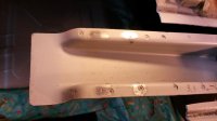
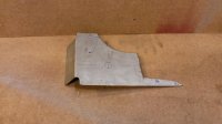
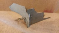
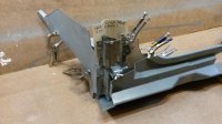
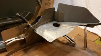
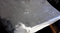
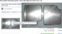
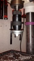
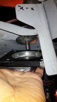
Now W&N offer a part, and I wonder if that is the part that I described in post #55.
http://www.wallothnesch.com/karosse...tore=eng&dir=asc&order=name&___from_store=eng
For the life of me, i can't figure out where else the W&N part would be located. But as the shape of the W&N part does not match the shape exactly in the pics of Vranedom's, nor does it show to be on the green car in the BMW museum (although the pic is too vague to be sure).

Questions:
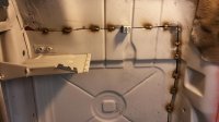
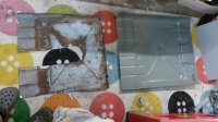
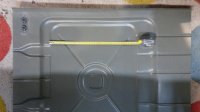
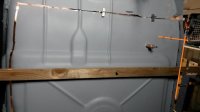
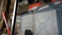
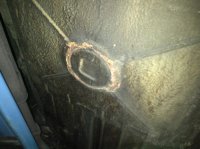
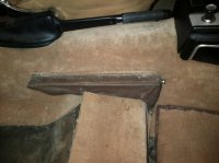
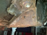
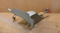
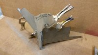
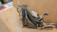
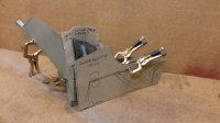
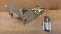
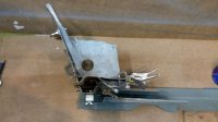
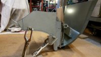
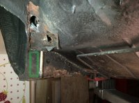
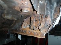
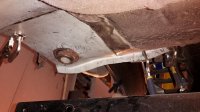
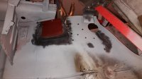
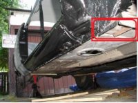
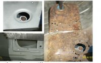
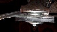
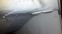
-Can someone confirm if the W&N part (pic 1) is the thing as the red squared part in the pic 2 below?
-what would be the purpose of this part? is it to locate a jack? If so, it is in a horribly weak location.

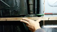
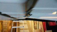
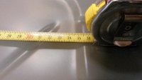
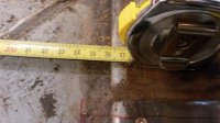
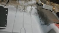
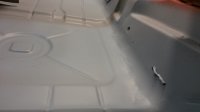
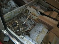
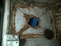
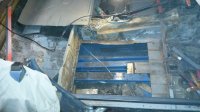
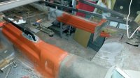
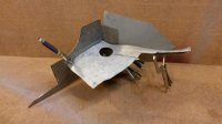
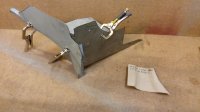
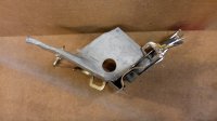
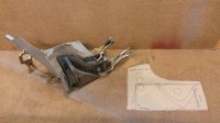
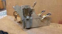
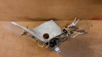
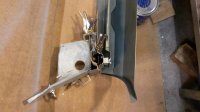
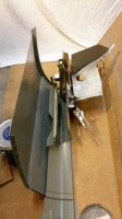
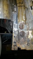
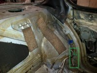
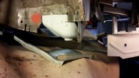
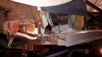
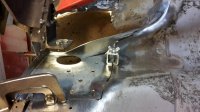
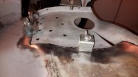
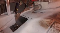
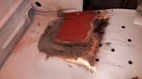
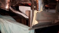
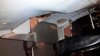
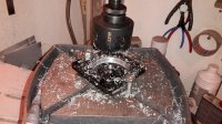
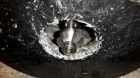
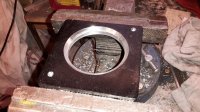
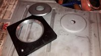
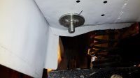
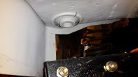
Pic 3&4 are current status of my build. I'm in the process to shape all the passenger side sill parts and making sure they fit 100% before continueing to weld. I want to be able to trial-build all the layers up to the last panel, to check that all is aligned & perfect before welding in the repair patches to the inner sill part and the inner wheelarch.
Note that in pic 4 there are some parts still missing, most importantly the outer skin :)wink:), but also a reinforcement that is running down from the outer wheel well onto the yellow intermediate sill.
 

Attachments

  • W7N Connection_sheet_lower_front_floor_panel_inner_sill_right_you_need_1_for_1_c.jpg
    W7N Connection_sheet_lower_front_floor_panel_inner_sill_right_you_need_1_for_1_c.jpg
    87.3 KB · Views: 305
  • http_vranedom.com_rockers_P6200014.jpg
    http_vranedom.com_rockers_P6200014.jpg
    20.5 KB · Views: 329
  • 20160104_222738.jpg
    20160104_222738.jpg
    94 KB · Views: 299
  • 20160104_220849.jpg
    20160104_220849.jpg
    89.9 KB · Views: 297
Last edited:

eriknetherlands

Moderator
Site Donor
Messages
2,697
Reaction score
1,929
Location
Netherlands, Eindhoven area
Why I was bogged down by knowledge

Being a purist wanting to have all details matched, I was disappointed to learn that I was missing a large depressed area in the last parts that I had just welded in.
Now this meant, to my horror, that a part of my car was not as it left the factory. And I can't have that ofcourse.

Here's a pic of the rear floor above the right subframe mounting point that I made some time ago, showing just a round hole. The second picture shows an original car and it's patch panel (courtesy CSL garage.com). This is what tied me in the garage for another 10 evenings.....

How do I get that depression into the part that I already have welded in the floor?
 

Attachments

  • 20151222_224636.jpg
    20151222_224636.jpg
    92 KB · Views: 277
  • Rear subframe mounting point original depression.jpg
    Rear subframe mounting point original depression.jpg
    19.5 KB · Views: 300
Last edited:

eriknetherlands

Moderator
Site Donor
Messages
2,697
Reaction score
1,929
Location
Netherlands, Eindhoven area
Making a steel pressing mould

To solve my issue of the missing depression, I also took the solution from the website of CSLgarage (http://www.powerfanatics.com/forum/viewtopic.php?t=964&postdays=0&postorder=desc&start=0)
use Google translate to your favorite languege so you can admire seriously talented E9 bodywork.

Here Miklos fabricated a stamping tool to form the correct shape. So that is what i setout to do as well.

Now I don't have a lathe, milling machine, or shop press, so I have to go MacGyver here.
I choose to create an aluminium die for the lower plate with a counter sink created with a router. The top plate will be a large washer. They both get a 45 degree edge.
Both dies will be supported by steel plates for strenght.
 
Last edited:

eriknetherlands

Moderator
Site Donor
Messages
2,697
Reaction score
1,929
Location
Netherlands, Eindhoven area
tooling fabrication

To create the correct depressions in the rear floor where the subframe mounts, i created this tool.

It was done with just DIY tools; the most exotic tool was the hole cutting saw in the right diameter (60mm; 15 euro's ) and the routerbit capable to mill aluminium (20 euro's).

pic 1, 60 mm hole in a 10 mm thick alu plate
pic 2, using a router to create a 45 degree angle
pic 3, resulting lower die
pic 4, the upper die was made with a large 3*60 mm steel washer. This needed to be a bit reduced in diameter, and a 45 degree angle was added. This was done by using the bench drill and an angle grinder.
pic 5, the resulting tool installed in a trial sheet; 0,7 mm steel
pic 6, result of a trial. It uses a M12 bolt for the pressing force. The use of a simple spanner is enough to give you the force needed to shape it.
pic 7, my car with new floor at the right rear subframe mounting point, showing the upper die in place, with an additional centering ring to keep the upper die from moving around.
pic 8 lower die, with a 10 mm thick steel backing plate to distriute the forces. The steel plate also has an M12 threaded hole on which the M12 bolt pulls.
pic 9 ready !
pic 10 with the inner reinforcement in place.
 

Attachments

  • 20160218_222823.jpg
    20160218_222823.jpg
    101.3 KB · Views: 303
  • 20160220_155515.jpg
    20160220_155515.jpg
    102.2 KB · Views: 308
  • 20160220_155437.jpg
    20160220_155437.jpg
    101.3 KB · Views: 318
  • 20160220_164327.jpg
    20160220_164327.jpg
    96.4 KB · Views: 293
  • 20160220_173446.jpg
    20160220_173446.jpg
    92.9 KB · Views: 303
  • 20160220_174307.jpg
    20160220_174307.jpg
    94.8 KB · Views: 316
  • 20160223_213121.jpg
    20160223_213121.jpg
    84.9 KB · Views: 375
  • 20160223_212941.jpg
    20160223_212941.jpg
    91.2 KB · Views: 366
  • 20160223_222416.jpg
    20160223_222416.jpg
    86.2 KB · Views: 292
  • 20160223_223847.jpg
    20160223_223847.jpg
    88.4 KB · Views: 380
Last edited:
Top