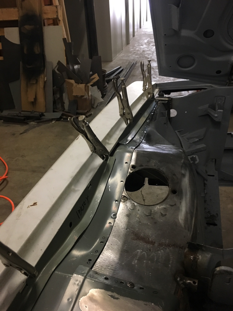
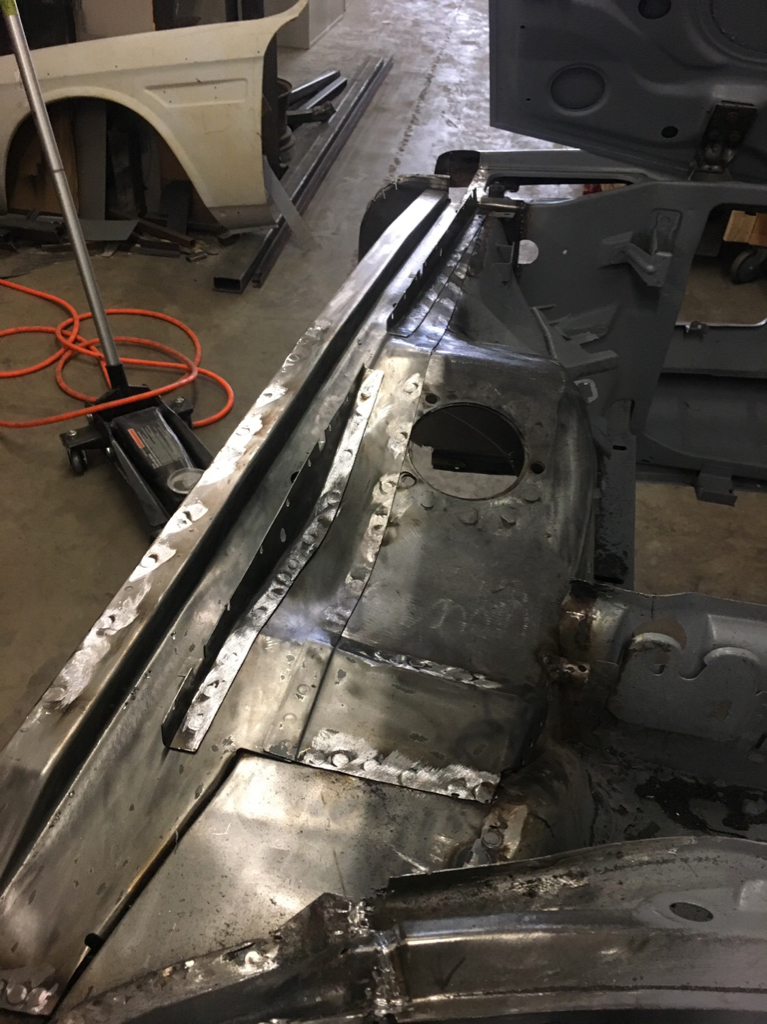
1974 BMW CSE

I am sorry to hear that. I am not on book face, and plan to keep it that way. If that makes me a dinosaur, I'm okay with it. :cool:

This car would have been junked or parted out if it wasn't for your passion.
I love what you are doing and the way you are doing it so please keep us informed and pick our brains for support.
Frequently this kind of troll behaviour is from people without the vision or talent to conceive and deliver a project like yours.
That said please don't ever do this to a CSL :eek:
 
Thanks guys, I feel the support!

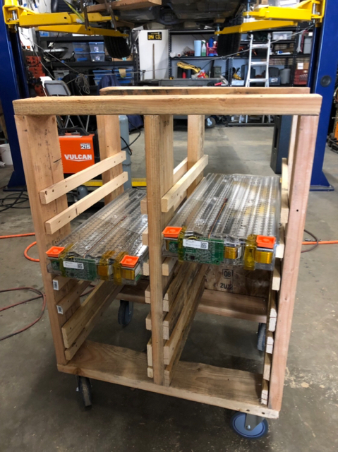
Yesterday I built the worst thing I have ever built- out of scraps and old pallets. But it will work just fine to load up our 14 Tesla battery modules for testing the drive unit and other systems before the modules can go in the car.

Maybe I’ll just put a trailer hitch on it and call it a day:)
b54cc95ee04b588d77203f09e4053355.jpg


Sent from my iPhone using Tapatalk
 
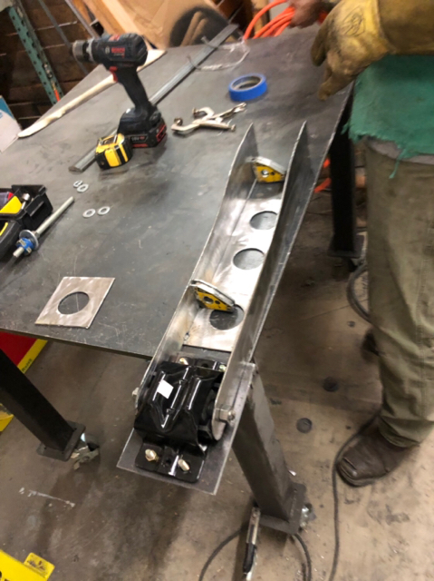
A beer for anyone who can guess where this critical robot-leg-looking assembly is going to go in the coupe.

If you have been following this thread closely you might be able to figure it out.

95d95b8e780c1a86bf23f7f2aada2a60.jpg


Sent from my iPhone using Tapatalk
 
A beer for anyone who can guess where this critical robot-leg-looking assembly is going to go in the coupe.

If you have been following this thread closely you might be able to figure it out.

95d95b8e780c1a86bf23f7f2aada2a60.jpg


Sent from my iPhone using Tapatalk
If I recall correctly, you've had to cut out a fair amount of the trunk floor and structure between the trunk and tunnel. My guess is that this will somehow attach to the tunnel and extend rearward to support the drive unit.?.
 
A beer for anyone who can guess where this critical robot-leg-looking assembly is going to go in the coupe.

If you have been following this thread closely you might be able to figure it out.

Sent from my iPhone using Tapatalk

Lift for front battery bay? I already regret my answer.

You seem to have thought of everything, but I was wondering whether you had or planned to provide additional support for the rear shock mounts? Sorry if I missed it, but it seems the rear engine mount structure and supports might increase forces on the vulnerable top of the shock mounts. This weakness was documented very early on these cars. https://e9coupe.com/forum/threads/heartbreak-broken-rear-shock-mount.18208/
 
Not quite the right answer yet- though one was very close. I'll give it till later this afternoon then I'll put a photo of it installed with the explanation. I guarantee it will be a "yes, of course" situation (and it's not overly technical).
 
looks like the yellow things suspend elec cables
The yellow things are magnetic squares - used for metal fabrication. They hold two parts square to one another in preparation to weld permanently. At least I think I have that answer correct! :D
 
Dang was closest with “Tunnel” though I found that to be a bit vague LOL. He gets half a beer:)

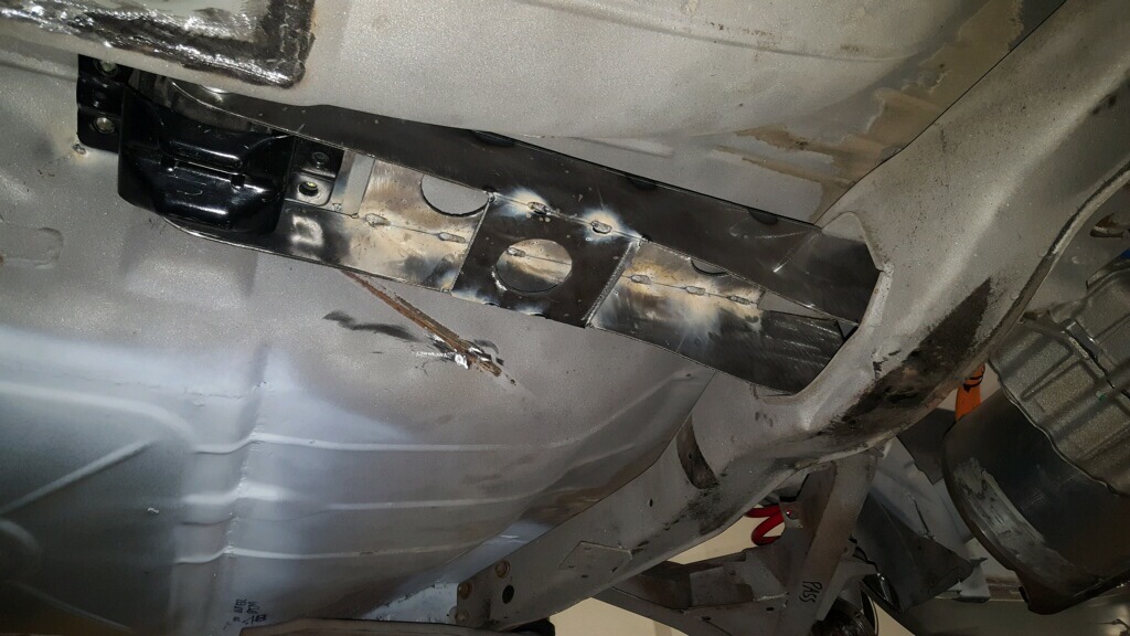
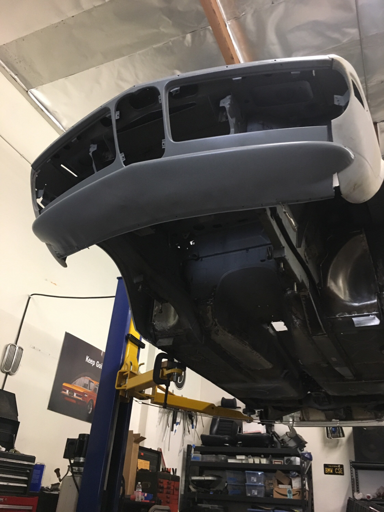
Since I have no differential, my rear suspension subframe mount no longer exists (as the differential is a bridge to form the mounting “tee” of the subframe).

So I had to replicate that tee forward into the tunnel. I found a Chevy motor mount to be a perfect solution along with our custom arm.

This photo shows it generally in place, but we haven’t finished welding it in.

c2cb8afc1d6faf2cb14bd624dc568811.jpg


Sent from my iPhone using Tapatalk
 
We did some test fitting of one of the new fenders and it is looking good. It is odd how the fit in a couple of places is pretty rough, like the rain gutter and the headlight bottom. But compared to what we have had to deal with it is nothing and the important stuff lines up beautifully.

95b8965ddcd6d1178543281297264b49.jpg
 
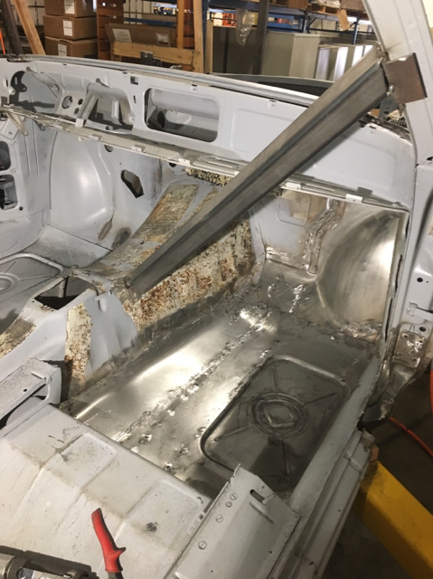
We finally have full floors! Today the last section of floor went in. Tomorrow we grind welds, brush and clean everything up and etch prime.

Right now they are floors only a mother could love:)

94817695860205c0e57fae4082eb529c.jpg
 
Considering you’re doing a major restoration of a car that’s notoriously difficult for the first time while fabricating body patches and unique parts to adapt systems from other cars and a freaking electric drivetrain, any mother should be proud. Oh, and you’re doing it all in record time with a Harbor Freight welder. (Granted it’s the nice HF welder.) Pretty amazing.
 
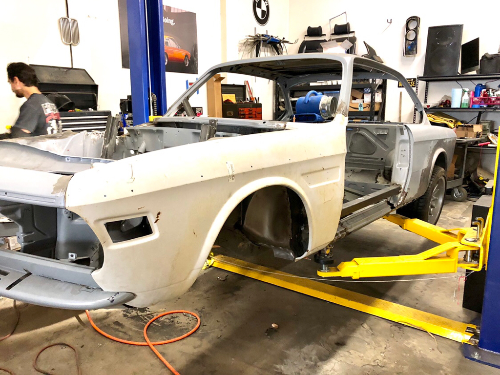
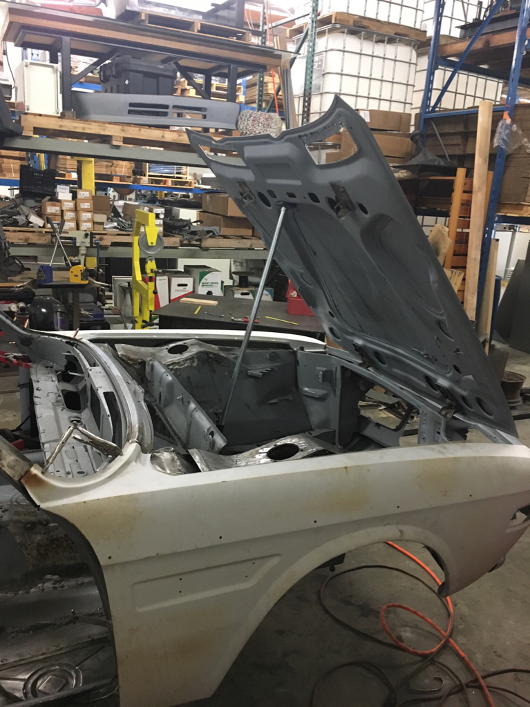
Wrapped up the inner fender work and started working on lining up hood to fenders to doors. That’ll take quite a bit of time. It’s starting to look like a shark again!

45eb3f2fcee0afbb7282d33abff7d8e1.jpg

8a69b3c3e00be9e6949b80d2a6fd7dc6.jpg

89e36230bd3161375e0f483ed2161b9c.jpg
 
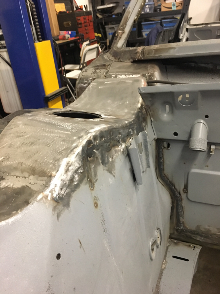
More work fitting the last of the inner fenders pieces now that we are aligning with hood and fenders. All the pieces are in but the short piece that spans from the firewall to the fender.

a771ad8583aa3146cdfb51b085c8ef5a.jpg


8fa0223a604c6577f683b9d390e7fdd4.jpg
 
We made some progress on the in-dash display. I am wanting to keep the classic look of the dash, but modern things up just a tad. Replacing the Tach section with our digital display. Showing MPH, Battery pull or charge, miles left on battery charge, regular or "insane" mode, cruise speed and such. Most of the things modern cars have. Of course the other gauges in the cluster will still function. I will convert the guts of the speedo to a pulse type so that it will function and look like stock. I'm planning on running the fuel and temp gauges as well for battery charge and temp.

Here's a fun little video of the progress: (the light grey looks blue in the video because of the phone camera- it is far less bright and blue in real life:)

 
Yeah, but does it talk to you like HAL 9000? "Just what do you think you're doing, Dave? Dave, I really think I'm entitled to an answer to that question." :)
 
Back
Top