Gorgeous work Jeff! You and Paul did some absolutely ground breaking work there. Congratulations!
You are using an out of date browser. It may not display this or other websites correctly.
You should upgrade or use an alternative browser.
You should upgrade or use an alternative browser.
1974 BMW CSE
- Thread starter JetDexter
- Start date
-
- Tags
- restoration list
Hello, you have completed one of a kind E9 I would say one of a kind BMW and you are very good father that you did all of this hard work for your daughter I don't know how old she is but when my daughter first start USC I bought her a brand new Audi A4 5speed back then all youngsters loved that Audi A4 but what you have for your daughter, Audi A4 is nothing compare to this one of a kind E9 I thing she is very happy with this car it is very nice car I thing if this car hit the BAT price tag will be over 250K however you are one talented guy, good luck with your CSETook it out for a drive the other day for some photos. Everyone who passed by loved it and a few asked if they'd be seeing it on BAT soon. No, I'm not selling it. Of course, no one knew that it was all Tesla under the covers. I have a punch list 50 items long of things to fix and finish. I lost gumption for a couple of weeks and I hate to tear the dash apart again to finish the instrumentation and HVAC but will dig in again soon. In the meantime...
View attachment 148100View attachment 148101View attachment 148102View attachment 148103View attachment 148104View attachment 148105View attachment 148106
How does one get the interior review mirror to snap back in? The spring on those detents is strong. My thumbs are sore.
Oh, and anyone doing a full resto -- don't forget to mount the rearview mirror support plate to the roof (three screws) BEFORE you do the headliner and mount the visor panel. Doh!
Oh, and anyone doing a full resto -- don't forget to mount the rearview mirror support plate to the roof (three screws) BEFORE you do the headliner and mount the visor panel. Doh!
I use a short piece of wood and my dead blow hammer!
Ouch. I feel that pain so deeplyOh, and anyone doing a full resto -- don't forget to mount the rearview mirror support plate to the roof (three screws) BEFORE you do the headliner and mount the visor panel. Doh!
After months of building circuits and subsystems and tearing things apart on the odd weeknight or weekend, I've finally made significant enough progress to post a small update. Skip if anything non-original tuns your stomach.
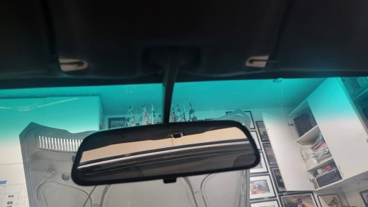
First, we got the rearview mirror in. You'd think that would be easy but it wasn't, since we forgot to mount the bracket to the roof before installing the headliner. I was able to get the bracket attached the roof by cutting a hole in the headliner through the mirror hole in the visor panel and slipping the bracket diagonally through the hole. Fortunately, the speed nuts were still in the roof so I was able to use an awl to locate the holes and angled the screw driver through the rectangular hole. If the nuts hadn't been there I'd be looking at pulling off so much stuff to get under there I'd have lost my mind. Fortunately, everything stretches just enough. Once the bracket was in I still had a hell of a time getting the mirror to snap in. Luckily Brett came over and used a scalpel to trim the headliner material a tad more and was able to twist the mirror in. Finally.
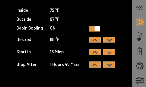
@JetDexter joined Brett and I on Saturday and we spent the day on wiring and A/C. Because I have an electric Tesla AC compressor, I added "Cabin Cooling" to the car. Using the touch screen (hidden behind the wood speaker grill, more on that later), you can set a desired cabin temp, a (optional) delay, and a duration and I'll kick on the A/C and blower fan as necessary to maintain that temp while parked. This means engaging the high voltage A/C contactor, turning on the DC/DC converter, turning on the condenser fan, sending a PWM speed signal to the AC compressor, sending the 12v+ and "enable" ground signals to the A/C compressor, and turning on the cabin blower fan, all with the key off and without inadvertently turning on anything undesired or feeding signals back into the HVAC ECU, etc.
Needless to say, it takes a computer, some temp probes, a few diodes, some opto-isolators, and a lot of relays. I haven't charged the system yet but the good news is that I have the A/C compressor engaging (jumping the binary pressure switch, just to test) and can control its speed. I'm 3D printing more A/C ducts now. It's all pretty cool (pun intended) because everything looks like a stock non-A/C car.
Admittedly, I have not added heat yet though. That's feasible but a project for next winter maybe. This is a SoCal car. And it has heated seats (but I haven't figured them out yet -- modern BMW seats require CANbus for everything).
We also wired up a lot of things that we either hadn't gotten around to before the wedding or hadn't fully finished, such as: the wipers (modern BMW column/switch), hazards (has soft touch 3 blink lane-change turn signals), dome light, alarm, power door locks, high beam indicator, tank (low voltage/range) light, high temp light (using red oil light for that one), and blinking charging light (orange alternator light).
I'm cleaning up all the wiring and will post a video of all the instrumentation and operation later. On the final stretch...
First, we got the rearview mirror in. You'd think that would be easy but it wasn't, since we forgot to mount the bracket to the roof before installing the headliner. I was able to get the bracket attached the roof by cutting a hole in the headliner through the mirror hole in the visor panel and slipping the bracket diagonally through the hole. Fortunately, the speed nuts were still in the roof so I was able to use an awl to locate the holes and angled the screw driver through the rectangular hole. If the nuts hadn't been there I'd be looking at pulling off so much stuff to get under there I'd have lost my mind. Fortunately, everything stretches just enough. Once the bracket was in I still had a hell of a time getting the mirror to snap in. Luckily Brett came over and used a scalpel to trim the headliner material a tad more and was able to twist the mirror in. Finally.
@JetDexter joined Brett and I on Saturday and we spent the day on wiring and A/C. Because I have an electric Tesla AC compressor, I added "Cabin Cooling" to the car. Using the touch screen (hidden behind the wood speaker grill, more on that later), you can set a desired cabin temp, a (optional) delay, and a duration and I'll kick on the A/C and blower fan as necessary to maintain that temp while parked. This means engaging the high voltage A/C contactor, turning on the DC/DC converter, turning on the condenser fan, sending a PWM speed signal to the AC compressor, sending the 12v+ and "enable" ground signals to the A/C compressor, and turning on the cabin blower fan, all with the key off and without inadvertently turning on anything undesired or feeding signals back into the HVAC ECU, etc.
Needless to say, it takes a computer, some temp probes, a few diodes, some opto-isolators, and a lot of relays. I haven't charged the system yet but the good news is that I have the A/C compressor engaging (jumping the binary pressure switch, just to test) and can control its speed. I'm 3D printing more A/C ducts now. It's all pretty cool (pun intended) because everything looks like a stock non-A/C car.
Admittedly, I have not added heat yet though. That's feasible but a project for next winter maybe. This is a SoCal car. And it has heated seats (but I haven't figured them out yet -- modern BMW seats require CANbus for everything).
We also wired up a lot of things that we either hadn't gotten around to before the wedding or hadn't fully finished, such as: the wipers (modern BMW column/switch), hazards (has soft touch 3 blink lane-change turn signals), dome light, alarm, power door locks, high beam indicator, tank (low voltage/range) light, high temp light (using red oil light for that one), and blinking charging light (orange alternator light).
I'm cleaning up all the wiring and will post a video of all the instrumentation and operation later. On the final stretch...
Attachments
Fascinating work, Jeff! Well done
Reading @Stevehose's thread on the engine noise, with the plethora of diagnostic suggestions and successful outcome made me reflect on problem solving in general and a recent debugging journey I've been on. I debug and solve problems for a living, around the house, as a hobby, and for my wife, even though she really just wants me to listen. What is it about us that we voluntarily take new problems into our lives?
Skip all this if you're a purist.
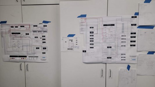
Reminder, I've written an app that can display various information from the CANBus on a screen that I've mounted in the hole where the now-irrelevant tachometer used to be. Recently, I've had a problem with the edges of the round Chinese DisplayModule DM-TFTR34-359-2 display with DM-ADTTR-014 driver board sometimes fading away and ghosting images.

Unfortunately, a million things have changed since this worked. And even when it was working, we saw this same issue a couple of times. Things that have changed: the driver board (the power connectors broke off two old ones), the mount (changed and re-printed the 3D model to make it more shallow so it will clear the defroster duct), the buck converter and its location (I mounted it to the gauge cluster so I won't have to plug/unplug and break another board), the power wiring (I added a Molex connector for display power, clock, and instrument lights, which weren't previously connected), the HDMI cable (I moved the micro computer to the rear seat so a long cable was necessary), all gauge/computer related wiring (extended to rear seat), power, ground, etc. connections in back, etc. Way too many things to isolate the problem based on "what changed".
As the photos above show, the problem is intermittent and occurred on the bench when I setup a simulation of the entire setup (long extension wiring,etc.). At that time, I thought it was because the screen was pinched around the outside by the glass bezel. I removed and reinstalled with various gaskets and tightening and thought I'd fixed it, but, as you can see, it still happened even when removed from the cluster and sitting flat. Then I thought it was the amperage from my benchtop 12v power supply being too low. I changed to a drycell 12v battery and it worked so I thought I was good but it was really just the intermittent nature fooling me again.
I didn't know that at the time and had installed the cluster into the car but two weeks ago the problem resurfaced. I did a quick test with a different micro computer, a different HDMI cable, and a different power source and it worked. Then I plugged it all back in and it worked from the back. I wasn't happy with "self resolution" of the problem but ignored it until last weekend when I reinstalled the gauge cluster and the problem was back. I must figure this out because I don't want to install all of the dash until I know it is fixed.
In desperation, I contacted the manufacturer of the display and they suggested I connect a Windows PC to the display in order to rule out display config issues with the Linux-based micro computer I'm using. Not super-helpful but not a bad idea either.
I connected a laptop with a short HDMI cable and it looked fine. It is a bit hard to tell because the Windows resolution is all wrong for the square display but the rectangle that is rendered appears to be clear and bright on the left and right sides.
This would appear to rule out anything forward of the laptop:
In hindsight, writing this up logically, I realize I chased a few red herrings along the way. I should've stopped and written this down sooner.
Figuring the HDMI cable to be the most likely suspect, I replaced the long HDMI cable and Micro-HDMI adapter with a single 6ft micro to HDMI cable from Amazon. This is one of the reasons I didn't work on the car all week -- I was waiting for the new cable. But I still had the faded edges. Furthermore, I used another of the same cable for the micro computer connected to the touch screen display behind the speaker, which works fine, so length doesn't appear to be the problem. That would appear to rule out #1 and #2.
Frustrated, I had an older model micro computer laying around, with a development operating system image SD card, the same short HDMI cable from the PC, powered by a USB hub. This worked. The edges were bright. Too many variables changed so no conclusion reached, other than micro computers in general don't appear to be the problem.
#3 was a concern. The display doesn't work at all on a micro computer without the proper configuration. I had that config already in the development SD card image but just to be sure, I pulled the SD card from the micro computer in the car and put it into the extra one. That also worked, which would appear to rule out #3.
But not entirely. In my research, I found some other settings such as hdmi_boost (which increases the amplitude and/or preemphasis of the HDMI signal) that I could try. Thinking that #4, the cable length, might be the problem, I changed the short HDMI cable on the extra computer to the original long one that I had already replaced, but that worked fine so I don't think I need to boost the signal and I think I've ruled out #4.
Moving on to #5, I put the SD card back into the original micro computer and attached my little 12v dry cell battery to the fuse block under the seat and my battery charger on the 12v battery in the trunk. 13.4v at the fuse block. I assume enough amperage. Still failed. Appears to rule out #5.
Moving on to #6, I unplugged the buck converter USB-C from the micro computer and used a USB-C-USB-2 cable to an A/C powered USB hub for micro computer power. Still failed. Appears to rule out #6, and #7 really.
Skip all this if you're a purist.
Reminder, I've written an app that can display various information from the CANBus on a screen that I've mounted in the hole where the now-irrelevant tachometer used to be. Recently, I've had a problem with the edges of the round Chinese DisplayModule DM-TFTR34-359-2 display with DM-ADTTR-014 driver board sometimes fading away and ghosting images.
Unfortunately, a million things have changed since this worked. And even when it was working, we saw this same issue a couple of times. Things that have changed: the driver board (the power connectors broke off two old ones), the mount (changed and re-printed the 3D model to make it more shallow so it will clear the defroster duct), the buck converter and its location (I mounted it to the gauge cluster so I won't have to plug/unplug and break another board), the power wiring (I added a Molex connector for display power, clock, and instrument lights, which weren't previously connected), the HDMI cable (I moved the micro computer to the rear seat so a long cable was necessary), all gauge/computer related wiring (extended to rear seat), power, ground, etc. connections in back, etc. Way too many things to isolate the problem based on "what changed".
As the photos above show, the problem is intermittent and occurred on the bench when I setup a simulation of the entire setup (long extension wiring,etc.). At that time, I thought it was because the screen was pinched around the outside by the glass bezel. I removed and reinstalled with various gaskets and tightening and thought I'd fixed it, but, as you can see, it still happened even when removed from the cluster and sitting flat. Then I thought it was the amperage from my benchtop 12v power supply being too low. I changed to a drycell 12v battery and it worked so I thought I was good but it was really just the intermittent nature fooling me again.
I didn't know that at the time and had installed the cluster into the car but two weeks ago the problem resurfaced. I did a quick test with a different micro computer, a different HDMI cable, and a different power source and it worked. Then I plugged it all back in and it worked from the back. I wasn't happy with "self resolution" of the problem but ignored it until last weekend when I reinstalled the gauge cluster and the problem was back. I must figure this out because I don't want to install all of the dash until I know it is fixed.
In desperation, I contacted the manufacturer of the display and they suggested I connect a Windows PC to the display in order to rule out display config issues with the Linux-based micro computer I'm using. Not super-helpful but not a bad idea either.
I connected a laptop with a short HDMI cable and it looked fine. It is a bit hard to tell because the Windows resolution is all wrong for the square display but the rectangle that is rendered appears to be clear and bright on the left and right sides.
This would appear to rule out anything forward of the laptop:
- Display
- Display board
- Display mounting squeeze
- 5v Buck converter powering the display
- 12v Power feed to display buck converter
- Male to female HMDI adapter/extension plugged into the display (which short HDMI cable from PC was plugged into)
- Long HDMI cable
- Micro-HDMI to Female HDMI adapter plugged into the micro computer
- Micro computer display configuration
- HDMI signal over a long distance
- 12v power or fuse block to buck converter
- 5v Buck converter powering micro computer
- Ground to buck converter
- Micro computer in the rear seat
In hindsight, writing this up logically, I realize I chased a few red herrings along the way. I should've stopped and written this down sooner.
Figuring the HDMI cable to be the most likely suspect, I replaced the long HDMI cable and Micro-HDMI adapter with a single 6ft micro to HDMI cable from Amazon. This is one of the reasons I didn't work on the car all week -- I was waiting for the new cable. But I still had the faded edges. Furthermore, I used another of the same cable for the micro computer connected to the touch screen display behind the speaker, which works fine, so length doesn't appear to be the problem. That would appear to rule out #1 and #2.
Frustrated, I had an older model micro computer laying around, with a development operating system image SD card, the same short HDMI cable from the PC, powered by a USB hub. This worked. The edges were bright. Too many variables changed so no conclusion reached, other than micro computers in general don't appear to be the problem.
#3 was a concern. The display doesn't work at all on a micro computer without the proper configuration. I had that config already in the development SD card image but just to be sure, I pulled the SD card from the micro computer in the car and put it into the extra one. That also worked, which would appear to rule out #3.
But not entirely. In my research, I found some other settings such as hdmi_boost (which increases the amplitude and/or preemphasis of the HDMI signal) that I could try. Thinking that #4, the cable length, might be the problem, I changed the short HDMI cable on the extra computer to the original long one that I had already replaced, but that worked fine so I don't think I need to boost the signal and I think I've ruled out #4.
Moving on to #5, I put the SD card back into the original micro computer and attached my little 12v dry cell battery to the fuse block under the seat and my battery charger on the 12v battery in the trunk. 13.4v at the fuse block. I assume enough amperage. Still failed. Appears to rule out #5.
Moving on to #6, I unplugged the buck converter USB-C from the micro computer and used a USB-C-USB-2 cable to an A/C powered USB hub for micro computer power. Still failed. Appears to rule out #6, and #7 really.
Last edited:
I didn't really realize I was down to just #8. I was still focused on the rear seat location. Fortunately, I mounted all these computers to that fiberglass board I made so I was able to unplug the CANBus connections in the rear, and disconnect the ground wire attached to the chassis and just lift the entire board into the front of the car. I jumped the ground on the fuse block to a terminal under the dash. At first it appeared to work, but there was an odd flash of blue on the screen. Then it was fine. WTF? Other than the CANBus being disconnected and the ground wire being different, this was the same configuration that had been failing consistently. I cycled the key and it was still ok. Looking good, just moved up front...
.png")
But, I had the board sitting partially on my lap and, at some point, I moved and the display faded completely! I wiggled the HDMI cable at the micro computer and I was able to make the display go blue or off completely. See video. https://youtu.be/gbGMLY8O5xE
It would appeared that the micro HDMI port on the micro computer was partially disconnected/flaky. As I wiggle the cable, you can see the display to go blue, go away completely, or return fine. I can't actually reproduce the faded edges problem but I was fairly certain this was the problem.
So, I harvested the micro computer from my other CSE project car and replaced it. I was so hopeful. But, upon getting everything all back into the car and hooked up, I still have the faded edges. I secured all the cables so there is no wiggling now. I even 3d printed a cable riser.
.png")
I also connected the old micro computer to a computer monitor with the old micro-HDMI adapter and it looks fine. Wiggling the connection doesn't affect the display. So maybe it was fine after all? Something else has a bad connection?
At this point, it would seem that either the problem is so intermittent that either I've ruled out things that I shouldn't have or the problem is associated with the CANBus, because that's the only difference. It worked, albeit with some blue screen flakiness but no faded edges, when the board was lifted out of the rear of the car. The only difference between that and now is the CANbus connections don't reach so they were disconnected, and ground was temporary.
After I wrote that, I figured I'd got back outside and see if disconnecting the CANBus cables makes a difference. All I did was turn the power back on and when I turned the key everything looks perfect. I did not touch the CANBus cables. WTF!!?? I went back there and wiggled everything I could but it made no difference -- it continued to look great. I cycled the key, opened and closed the touch screen, etc. All fine.
.png")
.png")
Now I'm back to square one -- an intermittent problem that has fixed itself. I can't trust any of the tests and am not sure what to do next.
I can still mess the hdmi_boost but if it worked up front with the long cable that wouldn't seem necessary? But maybe that was a lark?
But, I had the board sitting partially on my lap and, at some point, I moved and the display faded completely! I wiggled the HDMI cable at the micro computer and I was able to make the display go blue or off completely. See video. https://youtu.be/gbGMLY8O5xE
It would appeared that the micro HDMI port on the micro computer was partially disconnected/flaky. As I wiggle the cable, you can see the display to go blue, go away completely, or return fine. I can't actually reproduce the faded edges problem but I was fairly certain this was the problem.
So, I harvested the micro computer from my other CSE project car and replaced it. I was so hopeful. But, upon getting everything all back into the car and hooked up, I still have the faded edges. I secured all the cables so there is no wiggling now. I even 3d printed a cable riser.
I also connected the old micro computer to a computer monitor with the old micro-HDMI adapter and it looks fine. Wiggling the connection doesn't affect the display. So maybe it was fine after all? Something else has a bad connection?
At this point, it would seem that either the problem is so intermittent that either I've ruled out things that I shouldn't have or the problem is associated with the CANBus, because that's the only difference. It worked, albeit with some blue screen flakiness but no faded edges, when the board was lifted out of the rear of the car. The only difference between that and now is the CANbus connections don't reach so they were disconnected, and ground was temporary.
After I wrote that, I figured I'd got back outside and see if disconnecting the CANBus cables makes a difference. All I did was turn the power back on and when I turned the key everything looks perfect. I did not touch the CANBus cables. WTF!!?? I went back there and wiggled everything I could but it made no difference -- it continued to look great. I cycled the key, opened and closed the touch screen, etc. All fine.
Now I'm back to square one -- an intermittent problem that has fixed itself. I can't trust any of the tests and am not sure what to do next.
I can still mess the hdmi_boost but if it worked up front with the long cable that wouldn't seem necessary? But maybe that was a lark?
Last edited:
Since I wrote that, I tried some other things.
I booted up the car yesterday morning and had the edge fade, which I figured was good because I could troubleshoot.
I attached a keyboard to the micro computer, exited my app, and opened a terminal window so I could look up the IP address. Then I verified that the problem was still rear of the dash by swapping in the extra micro computer and long HDMI cable, back and forth. The problem was unique to the micro computer in the back (the extra one looked fine). See https://youtu.be/EP77UC0fUzo You can see some of the app image burnt in behind the terminal window in the video, as well as the edges fading on the terminal window.
Then I used my Mac to SSH into the micro computer and edit the config file. I set hdmi_boost to the max value of 7 and initiated a reboot of the micro computer from the mac.
When the micro computer rebooted, it had a ghost burn-in of the terminal window appear when the screen went dark as it was booting.
The fade got way worse over time and the burn-in was so great that I actually thought the micro computer wasn't rebooting, when in fact it was. It's just that the burn-in kept appearing during the black portions of reboot. See here: https://youtu.be/dbXcBtvzLsU And that burn-in lasted across multiple reboots and even a complete power down. It is in the display.
Eventually, the app came up and the edge fade was gone. But the screen was flickering a bit. I repeated those steps all the way down to hdmi_boost 1, where the flickering was mostly gone. Then I even commented out hdmi_boost entirely. Of course, the edges were fine through every change. Meaning there is no correlation between the hdmi_boost setting and the problem going away -- it just went away because of the reboot.
I verified this later in the day when I turned the car on again and had the fade. I just used the mac to reboot the micro computer and it came back fine. Perhaps it is related to something on initial boot/HDMI handshake? But I have no idea what that would be. The burn-in seems to be in some frame buffer? The config settings from the manufacturer do mess with the frame_buffer settings:
hdmi_pixel_freq_limit=400000000
hdmi_timings=800 0 40 12 40 800 0 12 12 12 0 0 0 60 0 44740000 0
hdmi_drive=2
disable_overscan=1
max_framebuffer_width=2560
max_framebuffer_height=2560
And they had some other settings I didn't use, that I can try I guess but the fact that it works after reboot would seem to indicate that the settings are ok?
#force_turbo=1
#gpu_freq=300
#core_freq=400
It's nearly impossible to figure out the problem when the problem keeps going away during testing.
It helps me to write this down so I've been taking notes as I go...
Today I powered up the car and had the fade.
I wanted to SSH into the micro computer to try some config changes but the DHCP IP address had changed so I had to attach a keyboard, exit the app, and note the IP address. The edges were really fading and my app remnants were "burnt in" but I was able to read the terminal window.
Then I did a sudo reboot. The screen was really "burnt in", showing fairly clear ghosts of my app and the terminal window as it rebooted but when the micro computer actually started sending a signal it came back fine but had some "shake".
This "bad on initial boot, ok after reboot" seems to be the pattern. It has the fade on initial power up. But if I reboot the micro computer via software it comes back fine. The display holds the ghosted image somewhere until power is cycled on it. If I actually cycle power on the micro computer it comes back bad.
I went to my mac and SSHed into both micro computers and opened their config files. The config for the round display had an hdmi_boost=5, which causes the shake so I commented that out and did a sudo reboot.
Before going out to the car micro computer again, I had the idea of using the old micro computer (that I though had the wonky HDMI connection but really doesn't) with the round display from my car, which I have on my desk to see if I can reproduce and/or test on the desk.
On initial connection, using my development sd card, I got nothing. Then I realized it didn't have the config settings from the Chinese so I sshed into it and edited the config file to add the same settings as the micro computer in the car. Still nothing. WTF?
I took the extra micro computer out to the car, connected it to a USB hub for power and plugged it into the HDMI cable from the car's round display. It looked fine.
Then I re-read the email from China and they said the "the MCU of the adapter of these two batches has been changed" so I swapped in a different display board (both the large one with the HDMI and USB power connectors and the small daughter board with the ribbon connectors. Sure enough, then it worked with my display and looked fine. This is strange because all the boards I have are new -- both old ones broke. But I think I bought in two different batches maybe. Regardless, that's a problem for Future Jeff.
Back to the car.... As a test, I added edited the config on the extra micro computer to add the settings from the Chinese config that I hadn't previously used. These settings are:
force_turbo=1
gpu_freq=300
core_freq=400
I then rebooted the extra micro computer and it still looked fine
I then SSHed into the car micro computer and added those settings to its config and rebooted. It still had the fade.
This leads me to believe that the extra settings have no effect.
Given that the extra (the old original) micro computer always seems fine when plugged into USB hub power and the HDMI extension from the round display I'm feeling that everything points to the rear seat somehow. Power, CAN, cables -- I'm not sure. But the fact that it is fine back there once soft rebooted is confusing.
I said writing it down helps. I just had an idea.
I went to the car and turned on the key. The fade was there. I cycled power on the micro computer but left the key on. (btw, I added a switch to the micro computer power so when I say I am cycled power to the micro computer I mean just the micro computers -- the rest of the car remains powered up, including the display). It had the ghosted image as it was powering up but once it sent a signal it was fine!
Humm.... I then turned the key off and cycled power to the micro computer. When I eventually turned the key back on it had the fade, as expected.
This led to one more test. With the key off I rebooted the micro computer via SSH from my mac. When I went out to the car and turned on the key it had the fade. Therefore, I'm guessing that every other time I have sudo rebooted it and the problem has gone away I must've had the key on. Which I think is true because I was usually in front of the displays with the mac on my lap.
So, I think I've narrowed the problem down. It happens when the micro computer is powered up but the display is off. If the display is on when it powers up it is ok.
This led to one more test. The extra micro computer connected to the round display in the car (dev SD card w/ round display config) powered up with display (ignition key) off. Sure enough, faded edges. This is in the front of the car, USB power, etc. Final test, with display on, cycle power on extra micro computer. Sure enough, has some ghosting on boot but comes back fine.
Interestingly, this isn't supposed to be the case because I have hdmi_force_hotplug=1 (and hdmi_drive=2). This tells the micro computer to use HDMI mode even if no HDMI monitor is detected. My best guess now is that there is some handshake between the micro computer and round display board that isn't happening when the display is off.
I can live with this. It just means that if I ever power off the entire car (which I've been doing a lot lately while working on it), I need to either have the key on when I power it back up or just turn the key on later and cycle power to the micro computers with my little switch. Not ideal but not the end of the world since there will be no need to power down the car once I'm finished --- my battery lover device charges the 12v battery from the Tesla batteries via the DC/DC converter when necessary. In fact, no worse than my E39 M5 that will fry the multi-function display board if the nav unit isn't unplugged before servicing the battery. Hell, I'm better than OEM.
At least I feel comfortable bolting the dash back together now because the problem isn't systemic to the display. One problem solved. Many more to go...
Wow, and I have been worrying about finding a short in the dash wiring related to hazard/turn signal!
Amazing project but when I read this I feel like an under-achieving nitwit?
Well, that certainly isn't the intention @Gazz . In fact, I've been trying to expose the all the stuff that doesn't go right or I mess up. There are many inspiring people on the forum but, IMHO, reading resto threads where everything just works gets boring. I'm talking to you @deQuincey ;-)
I am so amazed by all of this. Truly awesome.
But funny enough, the reason I bought an e9 was
1. Because I like the style.
2. Because it was german engineered (though think the rustprotection dept employed an italian/french/english bloke/gal)
3. BECAUSE IT HAS SIMPLE ELECTRONICS....
And now I read in the first part of jeff's post: " I booted up the car yesterday morning and had the edge fade, which i considered good as now i could troubleshoot".
Imagine calling the dealer when it doesn't run, well rephrase that, when it doesn't make faint humming noises:
Dealer:" Ah, I see sir. I'm sorry you're late for work now. Did you already reboot the car, Sir?"
Last edited:
Fair enuf.
But I will say -- don't under estimate the number of things that have to be properly torqued/aligned/fitted/lubricated/wired/adjusted/etc for the ICE to "run" and move. Lots of things can go wrong there that could keep you from getting to work, and that you can't easily find/fix. But I get and appreciate the sentiment.
The good news on this project is: the car has never been out of commission. It always "runs" and charges. All the flaky stuff has been in the instrumentation and HVAC, because that's were I've deviated from Tesla and "innovated" (to less than OEM standards).
That said, there's a lot to be said for cars without computers.
On a bit of a roll. Charged the A/C system yesterday.
This was a Euro non-AC car originally. We installed a Restomod Air Vapir 2 S system under the dash. This is a compact unit that fits fairly easily but requires significant reduction in glovebox size, eliminates the fresh air vent feature, and required a lot of custom 3D-modeled duct manifolds to get the defrosters connected. Certainly not a "bolt-in". One could debate the evap size and blower CFM vs stock. I'm not sure how it would compare on paper and I haven't had any time for real-world comparisons to the stock setup but we made it work and initial results are promising.


The original duct to adapt two hoses to the OEM center "knee freezer" rectangular vents needed to be changed when I went to install the control panel and realized there is no extra room on the sides. Another duct was necessary to reroute the dash hoses lower to clear the speaker grill actuator (again, more on that later). I have a 3D printer and I'm not afraid to use it. All in all, a lot of ducts. I still only have the knee freezing center duct for A/C but, unlike OEM, I can send dehumidified A/C air up to the defrosters.


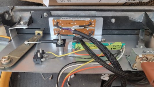
Restomod Air offers a dizzying array of ugly control knobs but I wanted as stick an appearance is was practical so I bought their "EZ CABLE INTEGRATORS W/ LINEAR SWITCH- 3SPEED BLOWER" kit to integrate with their ECU. It uses a 3-position switch for blower speed and linear potentiometers for the diverter and blend door. I designed an adapter plate to mount all that behind the original heater panel and some lever extensions to make the original black "knobs" fit properly on the pots and switch, and then had Send Cut Send laser cut those out. We welded the extensions to the switch and pots. I 3D printed a replacement "label panel" with A/C in place of vent and smaller slots for the sliding pots. I lost the label back-light (I tried but couldn't get it to shine through my printed panel) and the nice Blue-to-Red of the factory temp "wheel" but gained full control over compressor speed by turning the vent lever into a linear pot that controls the PWM speed signal to the Tesla A/C compressor. I like the fact that there is only one set of controls for heat and AC, unlike the dealer-installed AC system original to the cars. I also added a switch to the off position of the lever to enable running the blower without the A/C compressor.


We ran out of good places for the compressor so it ended up high in the engine compartment. The hose routing was less than ideal. The low pressure hose routes through the inner fender, with the charge port hidden behind the wheel and the high pressure side was a real challenge, requiring me to model up a complex adapter that I had milled out of aluminum to change the hose direction. It is designed with an o-ring slot, just as the the original adapter, which bolts to mine. Based on a recommendation from another forum user (whom I forget), I used Intellection Machine Works for the CNC milling and they changed the design a bit make it easier to mill. They are great for small batch machining (I have 4 more if anyone needs one). It works perfect to reroute the hose away from the fender/hood but was still a bit tight to the battery box. Even so, we were able to make it work, even adding the high pressure port there. All the hoses are the new smaller diameter, reduced barrier style, custom made by California Auth Refrigeration. The dryer (with binary switch) is located behind the right headlight and the parallel flow condenser is in front of the radiator as one would expect. We installed threaded bulkhead fittings to the firewall for each hose. Of course, all the hoses and fittings are the new o-ring style as there is no old flare stuff in the car.


Now, with all that fabrication/installation all done, it is finally time to charge up the system. This is a big step, as it commits me to not taking things apart again without some way of capturing refrigerant. I borrowed a friend's gauges and vacuum pump and used the Hack Mechanic's book as a reference along the way. I didn't have a bottle of nitrogen handy but pulled vacuum for 90 minutes and let it sit for half a day to verify no leaks. The compressor was used so had some oil but I added about an ounce more for good measure since the rest of the system is all new. Per the book, I only expected to get mid 40's from R134a but got down to 32 F with the compressor only at 40% speed. Better than I expected. Ambient was 69 F. Only took 12 oz of refrigerant. Both low and high pressure readings were reasonable, if a tad low. Running the compressor at full speed is loud and unnecessary. We'll see how it all works on a hot day.


This was a Euro non-AC car originally. We installed a Restomod Air Vapir 2 S system under the dash. This is a compact unit that fits fairly easily but requires significant reduction in glovebox size, eliminates the fresh air vent feature, and required a lot of custom 3D-modeled duct manifolds to get the defrosters connected. Certainly not a "bolt-in". One could debate the evap size and blower CFM vs stock. I'm not sure how it would compare on paper and I haven't had any time for real-world comparisons to the stock setup but we made it work and initial results are promising.
The original duct to adapt two hoses to the OEM center "knee freezer" rectangular vents needed to be changed when I went to install the control panel and realized there is no extra room on the sides. Another duct was necessary to reroute the dash hoses lower to clear the speaker grill actuator (again, more on that later). I have a 3D printer and I'm not afraid to use it. All in all, a lot of ducts. I still only have the knee freezing center duct for A/C but, unlike OEM, I can send dehumidified A/C air up to the defrosters.
Restomod Air offers a dizzying array of ugly control knobs but I wanted as stick an appearance is was practical so I bought their "EZ CABLE INTEGRATORS W/ LINEAR SWITCH- 3SPEED BLOWER" kit to integrate with their ECU. It uses a 3-position switch for blower speed and linear potentiometers for the diverter and blend door. I designed an adapter plate to mount all that behind the original heater panel and some lever extensions to make the original black "knobs" fit properly on the pots and switch, and then had Send Cut Send laser cut those out. We welded the extensions to the switch and pots. I 3D printed a replacement "label panel" with A/C in place of vent and smaller slots for the sliding pots. I lost the label back-light (I tried but couldn't get it to shine through my printed panel) and the nice Blue-to-Red of the factory temp "wheel" but gained full control over compressor speed by turning the vent lever into a linear pot that controls the PWM speed signal to the Tesla A/C compressor. I like the fact that there is only one set of controls for heat and AC, unlike the dealer-installed AC system original to the cars. I also added a switch to the off position of the lever to enable running the blower without the A/C compressor.
We ran out of good places for the compressor so it ended up high in the engine compartment. The hose routing was less than ideal. The low pressure hose routes through the inner fender, with the charge port hidden behind the wheel and the high pressure side was a real challenge, requiring me to model up a complex adapter that I had milled out of aluminum to change the hose direction. It is designed with an o-ring slot, just as the the original adapter, which bolts to mine. Based on a recommendation from another forum user (whom I forget), I used Intellection Machine Works for the CNC milling and they changed the design a bit make it easier to mill. They are great for small batch machining (I have 4 more if anyone needs one). It works perfect to reroute the hose away from the fender/hood but was still a bit tight to the battery box. Even so, we were able to make it work, even adding the high pressure port there. All the hoses are the new smaller diameter, reduced barrier style, custom made by California Auth Refrigeration. The dryer (with binary switch) is located behind the right headlight and the parallel flow condenser is in front of the radiator as one would expect. We installed threaded bulkhead fittings to the firewall for each hose. Of course, all the hoses and fittings are the new o-ring style as there is no old flare stuff in the car.
Now, with all that fabrication/installation all done, it is finally time to charge up the system. This is a big step, as it commits me to not taking things apart again without some way of capturing refrigerant. I borrowed a friend's gauges and vacuum pump and used the Hack Mechanic's book as a reference along the way. I didn't have a bottle of nitrogen handy but pulled vacuum for 90 minutes and let it sit for half a day to verify no leaks. The compressor was used so had some oil but I added about an ounce more for good measure since the rest of the system is all new. Per the book, I only expected to get mid 40's from R134a but got down to 32 F with the compressor only at 40% speed. Better than I expected. Ambient was 69 F. Only took 12 oz of refrigerant. Both low and high pressure readings were reasonable, if a tad low. Running the compressor at full speed is loud and unnecessary. We'll see how it all works on a hot day.
Another amazing story of dedication and intellect creating solutions to challenging issues.
wonderful work theres no other setups that are even close to the extreme thought
and process setup here.
the chroming of the rear license mounting brackets shows the detail thought out.
is it just lucky that the battery fits so well in the front area?
very super car .
goood job wonderful to watch progress.
with all this information detailed here its a marvel
install.
one thing not mentioned yet is the
END POINT !!! THIS CAR IS going to
simply hall ass as these motors are
out of this world.
i can wait to see half of the tires tread left on the
road when you punch the throttle!!!
Last edited:
Thanks for the kind words @aearch .
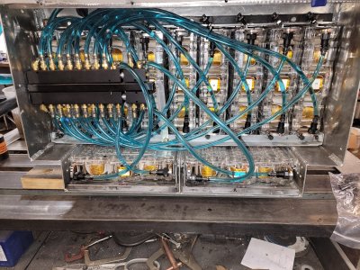
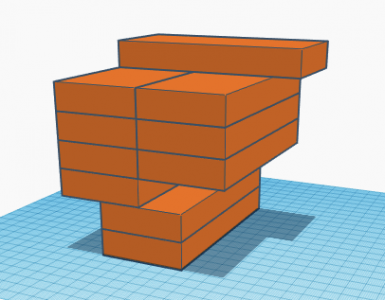
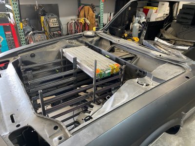
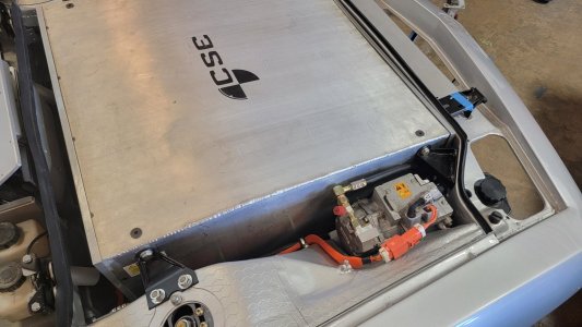
Finding room for the batteries is the hardest part on these conversions so, no, it is not coincidence that the box just fits. A Tesla drive unit requires between 270 and 370 VDC so you have to use batteries that provide that much voltage. There are batteries from LG Chem, Chrysler Pacifica minivans, Chevy Volts, etc, that can get you there but none have the energy density (or kWh) of the Tesla battery modules. If you want range then Tesla is the way to go. Trouble is, each Tesla module is only about 26 VDC so you need at least 14 modules. The modules are rectangles, about 27"x12"x3" each. Square things don't like to fit in irregular openings so fitting 14 of these into an e9 is an exercise.
The silver car discussed here fits 12 up front and 2 below the package tray in back. The front box has two batteries flat at the bottom, 9 on their side above that, and one laterally on top. To get all 12 to fit we had to replace the factory steering box with a rack and pinion unit from a Volkswagen and relocate the brake master and booster into the trans tunnel.


In my blue car, I managed to get 10 modules up front while still keeping the original steering box and slightly moving the brake master and booster over to the left. Then I fit 4 modules under the package tray. I did not use a 3D scanner and CAD for this. Instead, I have 14 foam blocks of battery size.


Some people stack the modules directly on top of one another but the cells are only protected from shorting by a clear plastic cover. I prefer to mount them by the mounting rails on the side and leave an air gap between each module. I also lock them into the rail supports. Then you must leave enough room and access to attach the bus bars and coolant hoses. You can see that 9 of the modules are on their side in the silver car but all are flat in the blue (black primer) car. Both cars have one sideways on top. There isn't enough room for them to be sideways lower in the engine compartment. Both cars required a very slight relief to the hood bracing.
As for performance, you are correct -- it is eye watering. I hope to post a video sizzle reel with driving shots soon. In the meantime, this was prior to getting the ride height dialed in, etc.
Finding room for the batteries is the hardest part on these conversions so, no, it is not coincidence that the box just fits. A Tesla drive unit requires between 270 and 370 VDC so you have to use batteries that provide that much voltage. There are batteries from LG Chem, Chrysler Pacifica minivans, Chevy Volts, etc, that can get you there but none have the energy density (or kWh) of the Tesla battery modules. If you want range then Tesla is the way to go. Trouble is, each Tesla module is only about 26 VDC so you need at least 14 modules. The modules are rectangles, about 27"x12"x3" each. Square things don't like to fit in irregular openings so fitting 14 of these into an e9 is an exercise.
The silver car discussed here fits 12 up front and 2 below the package tray in back. The front box has two batteries flat at the bottom, 9 on their side above that, and one laterally on top. To get all 12 to fit we had to replace the factory steering box with a rack and pinion unit from a Volkswagen and relocate the brake master and booster into the trans tunnel.
In my blue car, I managed to get 10 modules up front while still keeping the original steering box and slightly moving the brake master and booster over to the left. Then I fit 4 modules under the package tray. I did not use a 3D scanner and CAD for this. Instead, I have 14 foam blocks of battery size.
Some people stack the modules directly on top of one another but the cells are only protected from shorting by a clear plastic cover. I prefer to mount them by the mounting rails on the side and leave an air gap between each module. I also lock them into the rail supports. Then you must leave enough room and access to attach the bus bars and coolant hoses. You can see that 9 of the modules are on their side in the silver car but all are flat in the blue (black primer) car. Both cars have one sideways on top. There isn't enough room for them to be sideways lower in the engine compartment. Both cars required a very slight relief to the hood bracing.
As for performance, you are correct -- it is eye watering. I hope to post a video sizzle reel with driving shots soon. In the meantime, this was prior to getting the ride height dialed in, etc.