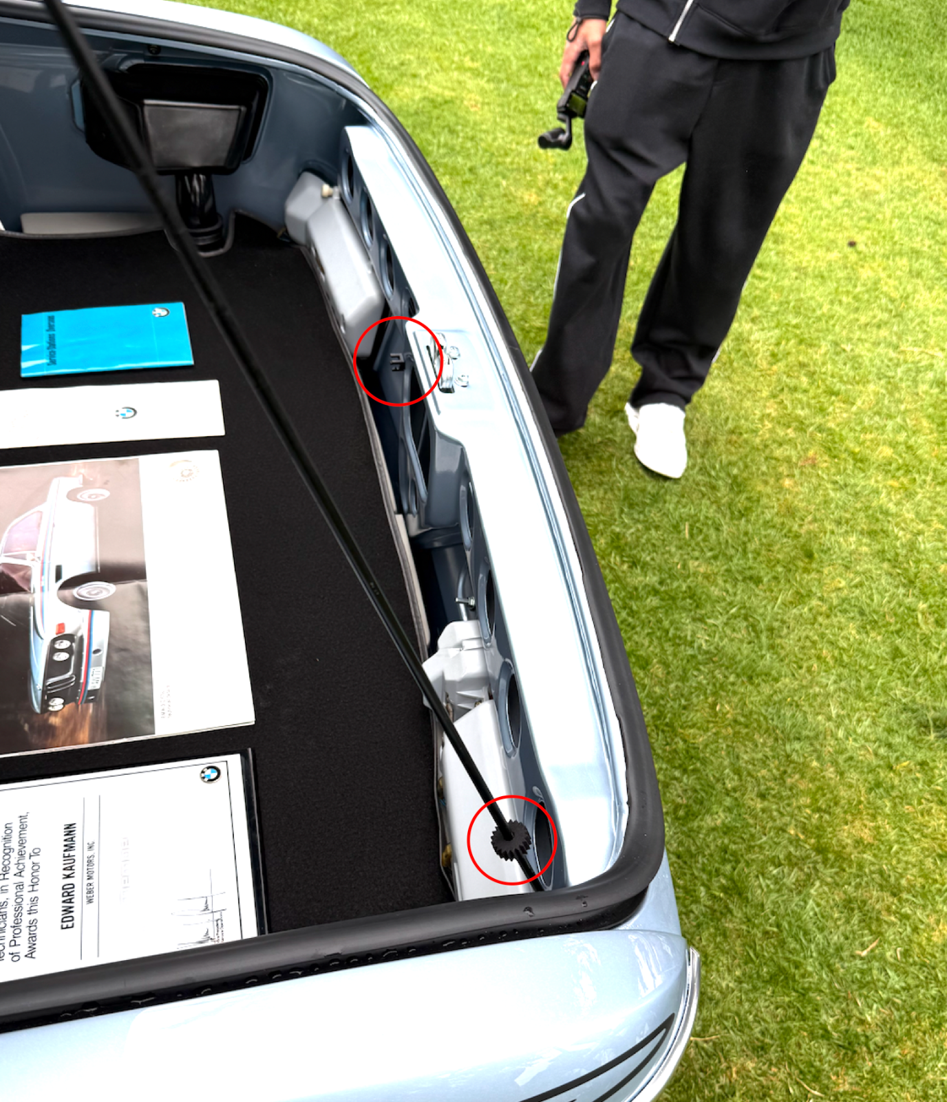
72 3.0 CS 2240344 Restoration

And I am proud to have contributed two eensty weentsy little parts to this effort.
Screenshot 2026-08-13 at 10.35.12 PM.png


Truly a beautiful car...
 
Question for the hive mind...

I am ready to refinish my suspension parts.

Subframes are empty and cleaned, trailing arms are disassembled, strut tubes are disassembled, etc.

I am wondering about two interrelated questions:

1) Is it better to paint these parts using 2K primer and 2K satin black paint, or should I powder coat them?

2) If I powder coat them, how to I make sure they are masked off in the right places (spindles, strut to knuckle, caliper mounts, strut tube threads, bushing holes, ball joint holes, etc...)?

I know many folks do powder coat, but it seems that you have to leave a lot to the powder coater who will blast them, clean them, and hopefully mask the right spots prior to coating...not sure how much I trust them to do that properly...

And then there is the question if the power coating gets chipped or is improperly adhered in some spot, does that create a potential rust haven? Seems like pain maybe easier to deal with..

Thoughts?
 
I would think that the powder coater would know their stuff, but one option would be for you to mask off what you don’t want coated and take a picture of each area which you print out and give them with the part. “Blast it, mask it off as per these pictures and coat the rest” will be your instructions
 
I would think that the powder coater would know their stuff, but one option would be for you to mask off what you don’t want coated and take a picture of each area which you print out and give them with the part. “Blast it, mask it off as per these pictures and coat the rest” will be your instructions
Yeah, that might work. I think the proper way to prep them is probably a metal dipping process. Alkaline, acid, wash, passivate.. I found a local place that does that, and I think the powder coater also does it. So maybe I can do as you say, and then go inspect them before they coat them, to be sure they have masked everything that needs masking.

I am assuming most metal mating surfaces would not get coated...
 
An auto painter who doesn't mask mounting holes isn't a real painter...
Any reputable painter—whether working with traditional paint or powder coating—is obliged to plug and protect all mounting holes and threads.
Powder coating is far more durable than standard paint finishes.
Coating defects or chips can be touched up and corrected, but the fix won't be permanent.
If the budget allows, one might consider Cerakote technology.
 
I had the front sub-frame powder coated and really had only two areas of concern on re-assembly. The first was the rubber mounting for the tension strut (#5 in the picture below). I did not ask them to tape the area and had a hell of a time getting the rubber back in. It is notoriously difficult and I could not get it installed, I ended up with a polyurethane / Delrin bushing instead and while I try to stay away from them it has been fine.

The second area that caused an "issue" was the spreader (#12) in the picture below. The clearance was too tight and I scratched the finish on installation. I was concerned that the tab for the sway bar was going to be too tight, but it was fine.


1786807656230.png
 
Forget powder. Use a heat cured cerakote. It was developed for rifle barrels. Amazingly hard. Doesn't chip. The coating is so thin that you don't have to mask or tape anything. The entire part gets coated. Both of my best powder coasters over the years have switched to Cerakote. Powder offers more color options but for most stuff it doesn't matter. Can also fill pits with JB weld,sand and recoat.
 
Forget powder. Use a heat cured cerakote. It was developed for rifle barrels. Amazingly hard. Doesn't chip. The coating is so thin that you don't have to mask or tape anything. The entire part gets coated. Both of my best powder coasters over the years have switched to Cerakote. Powder offers more color options but for most stuff it doesn't matter. Can also fill pits with JB weld,sand and recoat.
Looks like a good solution! I was going to Cerakote my headers, but looks like I should just do everything in that.
 
The heat cured is the way to go. Air cured is nice but no where near as durable. We only use that if the part can't be baked in the oven. It's really sweet to assemble something that has not been powder coated.
 
I'm surprised Cerakote hasn't become more ubiquitous in various industries. It's really amazing stuff, and not much harder to prep for compared to paint or powder.

I don't have a blast cabinet, so my surface prep at home is a compromise. Despite that, I've had really great results coating everything from hardware to hard parts. I've had a similar experience as Rudy with the air vs. oven cure. My scientific oven @ home is only ~16"x16"x16", so the larger stuff needs to be air cured, or outsourced to a local shop.
 
Off topic;

My son, who works at Tesla, recently gave me his 2022 Model Y (He got a newer one). We shipped it to Austin TX where we have place to stay when visiting the grandkids (which my wife Susan does regularly). Anyway, we have been here for about 10 days using the car to pick up kids from school and such, in those busy days before the school year starts.

Today Susan was picking up one of the boys and when she opened the car the doors made a weird noise. She got in the car and it was dead.. as in zippo response. She called, I went online and we tried all of the suggested fixes...numerous non-intuitive steps like push and hold the brake pedal, push the two scroll knobs at the same time, etc, etc.. Nada... Zilch...

After some calls to Tesla, and AAA we determined that the 12 volt battery had died.

I suggested she just leave the car and call an Uber, but she pointed out that since normally the windows roll down slightly when the doors open or close, and since they were up, the doors would not close.. WhoTF makes a car that you cannot secure even if the battery is dead???? Apparently the software obsessed geeks at Tesla do...

The AAA guy showed up after 2 hours, and apparently did not have a jumper cable or a battery pack (WTF? again). The service center was now at closing time.. A friend who also has a Tesla went to an auto parts store and got a battery jumper pack, and went over to the car. Apparently this is a thing with Teslas.. you pop open the tow hook port and there are a couple of wires that you can hook to a power source to pop open the"frunk", which then gives you access to the 12 volt battery.

They then hooked up the booster pack to the battery and the car booted up, the windows responded so we could both close the doors and drive the car.. We'll have the battery replaced sometime next week, since we are off to Chicago tomorrow AM early.

The core issue that boils my blood here is who on earth would design a car that you cannot close and lock the doors on if the battery dies? This car is a magnum opus of electronic control of everything, but the problem with that is that if anything goes wrong the car is a dead brick. If not for our friend, my wife would have had to leave the car in a parking lot overnight with the doors open (not unlocked, OPEN), until after changing our flights we managed to get a service person there to address the issue.

As soon as this car is functioning again, I am selling it and getting another Audi. MY 2007 Audi never failed to do anything ...I gave it to a relative in 2018. My 2018 Audi has been flawless ever since. I'm taking it to Austin to replace this POS Tesla, and I'll get a new Audi to drive at home...

There is definitely a boundary of too much reliance on electronics, and once crossed beware!!!
 
My wife has a 2018 model S. The key fob battery was at the end of life (it didn't notify ahead of time) and while she was back at the car after an activity the alarm triggered with horns blowing and the stereo playing classical music at full blast. She has had it, I am now under orders to sell it.

She really likes plugging it in at the house rather than stopping at the gas station (keep in mind that +/- 95% of the time I filled her cars up for her), but she is not a fan of the almost complete lack of physical controls, everything is accessed from the touch screen.

By the way, I have a 2018 Audi Q7. Last week it notified me on the dash that it was time to replace the key fob battery...
 
Apparently the latest version of this car has no control stick either. Instead of flipping the lever to go forward or back, you swipe on the touch screen. Sounds like a very bad idea...

I have worked in the auto industry since the early 1990's. Almost every safety critical system either has some mechanical backup, or it has internal redundancy, so if anything fails, it either fails safe, or it continues to work and warns you that it needs service. I did an electric power steering system in the early 1990's. It used a ball-screw rack, and just added torque boost to the already mechanical linkage, so if the motor or the drive electronics failed, you could still steer the car.

I also did a touch based interface for Ford back in the early 1990's. That was interesting since I experimented with a mouse, a track ball, and a touch screen before landing on a touch pad that had tactile regions that corresponded to selectors on the screen. So, you could control the selectors on the screen by simply touching the corresponding area on the touch pad in the center arm rest console. Easy to grasp, and easy to control because your hand is not bouncing around as you try to hit a target on the screen that is also bouncing around.. (I am reluctant to part with my 2018 Audi for this reason, the newer models use a touch screen, and it suffers from this same issue - one that has been known for 30+ years!)

My Audi has a very convenient, touch based lock/unlock feature on the exterior door handles..but the key fob still has a tiny manual key to be used in case something in that electronic system fails...and yes, it also warns me when the fob battery is low...

From the first day I drove the Model Y I was non-plussed. Harsh ride, harsh regen braking with no way to adjust it, non-intuitive controls, simple things buried 2 -3 layers deep in a touch screen menu... and that nice super clean dash with air vent controls set one layer into the menu screen using a touch and pinch gesture, so you can no longer just twiddle the vent to what you want.. you twiddle the screen and see how that feels, and then twiddle some more... because there is only a conceptual linkage between what is shown on the screen and what is actually blowing at your face...Too much software with too little thought given to how people operate...

Tesla seems to be headed down a dark overly software focused approach developed by geeks that probably don't even own a car, and apparently never heard of FMEA...
 
Back home now from my grand tour of the grand-kids...

Trying an experiment. Like many others, my inner CV boot flanges (the ones that attach the half shaft side of the differential side CV joint) are all mis-shaped from many years letting the wheels droop down when jacking the car.

I got some new boots that came with the flanges (Rein), but as others have pointed out, these have the raised dimples, requiring the dog-bone shaped bracing pieces, instead of the flat ones I have.

I decided to take a whack at re-shaping the originals. They are otherwise in good condition.

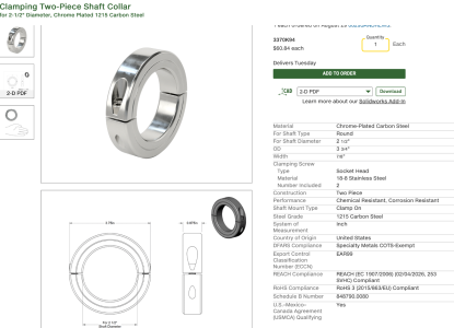
So, I purchased a two-piece shaft collar with the same ID as the flange OD, and a short bit of tubing with the same OD as the flange ID.

I plan to put the tube inside the flange, and place the collar around the flange and tighten the two halves of the collar, probably while moving the collar around the flange a bit at a time. I am hoping this re-rounds the flange, so it can be cleaned and re-used.

I may need to start with a somewhat larger collar.. We'll see...

I'll keep y'all posted!!
 

Attachments

  • Screenshot 2026-08-29 at 5.40.23 PM.png
    Screenshot 2026-08-29 at 5.40.23 PM.png
    503.4 KB · Views: 16
Well, my idea above sort of worked. For the flange that was sort of out of round, it straightened it up fairly well. Not perfect, but much better than better than it was. The other one is heavily distorted, and I did get it to look better, but it is not only out of round, but also crooked, so the axis of the CV side is not aligned with the axis of the boot end. It is better, but not really usable...

Sigh...
 
Last edited:
Update onthe great clock replacement project.

Several posts above I described revising the gauges on the left most cluster gauge with an oil pressure gauge and a voltage gauge. This replaces the clock in the right-most position of the cluster.

After mucking around with the temperature gauge, which seems to obey some alien laws of electronics, I located an antique Porsche gauge also made by VDO. This has a native oil pressure gauge that uses the same 10-180 ohm VDO oil pressure sender that many European cars use.

These combo meters are "handed", so the meter on the right side of the gauge runs counter-clockwise, with high being up and low being down, and the meter on the left side running clockwise, still with high being up and low being down.

The original gas gauge was a left side (CW) meter, and the temp gauge was right side (CCW) meter.

The Porsche oil pressure gauge was the CCW (right side) type, so I was then able to re-purpose the gas gauge to display volts..

Easier said than done...

I am still not 100 clear on how these meters work, but they appear to have three wires coming from the movement. In the original application (fuel level) the + side of the meter was connected to the battery voltage, one end was connected to ground, and one intermediate wire was connected to the variable resistor in the fuel level sender. So rather than sensing voltage, they are set up to sense resistance.

Converting this to read volts from the battery was something of a puzzle. I could get it to respond by connecting the + terminal to the battery voltage source (variable so I could tests the meter), and connecting ground to the G terminal. Connecting anything to actual case ground had no effect, but you had to have one of the tiny meter movement wires connected to case ground, or the meter would not work.. Don't ask me why...

The core issue I faced was that the meter was actually very linear. I could put a resistor in the battery line that would just peg the meter at 16 volts, but then the scale was from there to 0 volts at the other end. In a car any battery below about 8-9 volts is effectively useless, so having a volt meter that told me that the battery was between 8 and zero volts was pretty useless, and then the difference in pointer position from 12 to 14 volts (the range we really care about) was minuscule.

So, how to create a nonlinear drive for the meter movement? Normally with a solid power supply, this would be easy, just make a circuit that bends the voltages in the way we want.. But in this application the basic idea is that the battery voltage in what is being measured, so we can't design a circuit that depends on a known and fixed battery voltage to function, because that will not be there when we need it..

After dinking around with various diode circuits to try to either steer the current through different resistors to change the range , or to create a nonlinear circuit (both of which ended up requiring negative resistor values), I realized I could simply shift the scale of the meter to the relevant range using as zener diode.

A zener diode acts like a regular diode, except in reverse bias it breaks down and conducts at a specific voltage. So, when the applied voltage is above the zener voltage the diode conducts to set the voltage drop at whatever the zener voltage is (this is a selectable value depending on the diode chosen). Below that value, the diode acts like regular reverse biased diode, that is, it doesn't conduct any current, and the meter goes to zero.

If what we really care about is voltages above, say, 8 volts, then we put an 8 volt zener diode between the meter movement and ground. This means that as long as the voltage applied to the meter is above 8 volts, then the zener will conduct, and a rising applied voltage will cause the meter to move higher, but when the applied voltage drops below the zener voltage the diode does not conduct and the meter will go to zero.

The circuit looks like this:

Screenshot 2026-09-02 at 7.16.45 AM.png


And the behavior looks like this:
Screenshot 2026-09-02 at 7.16.32 AM.png


So, I need to redo my gauge labels to support this new scale. Here is what I am thinking:

Screenshot 2026-09-02 at 7.35.34 AM.png
 
Last edited:
Back
Top