CSL Restoration

Marc-M

Well-Known Member
Messages
377
Reaction score
311
Location
Preston - Lancashire-UK
Building up the nose cone is turning into quite an epic task.

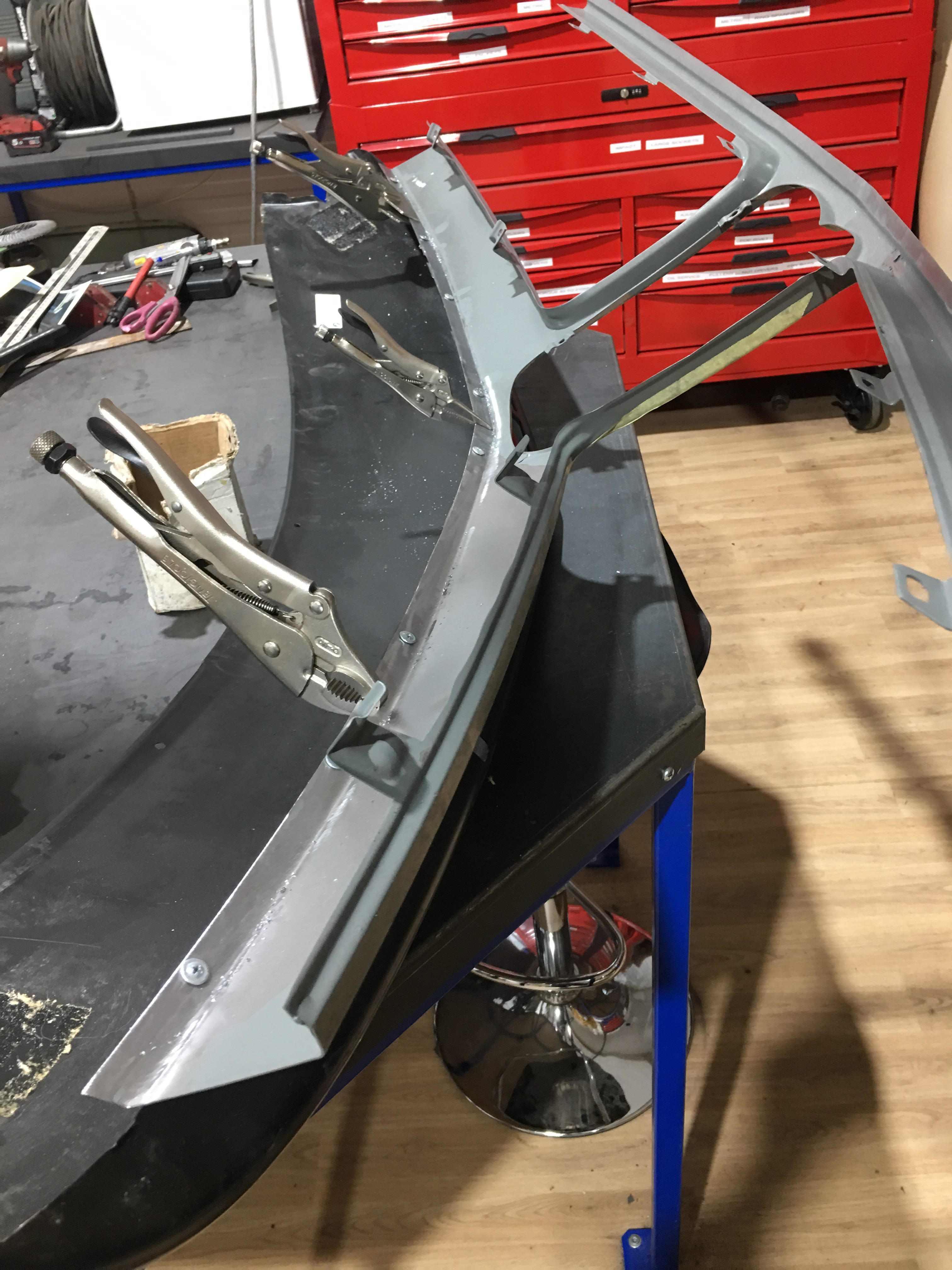
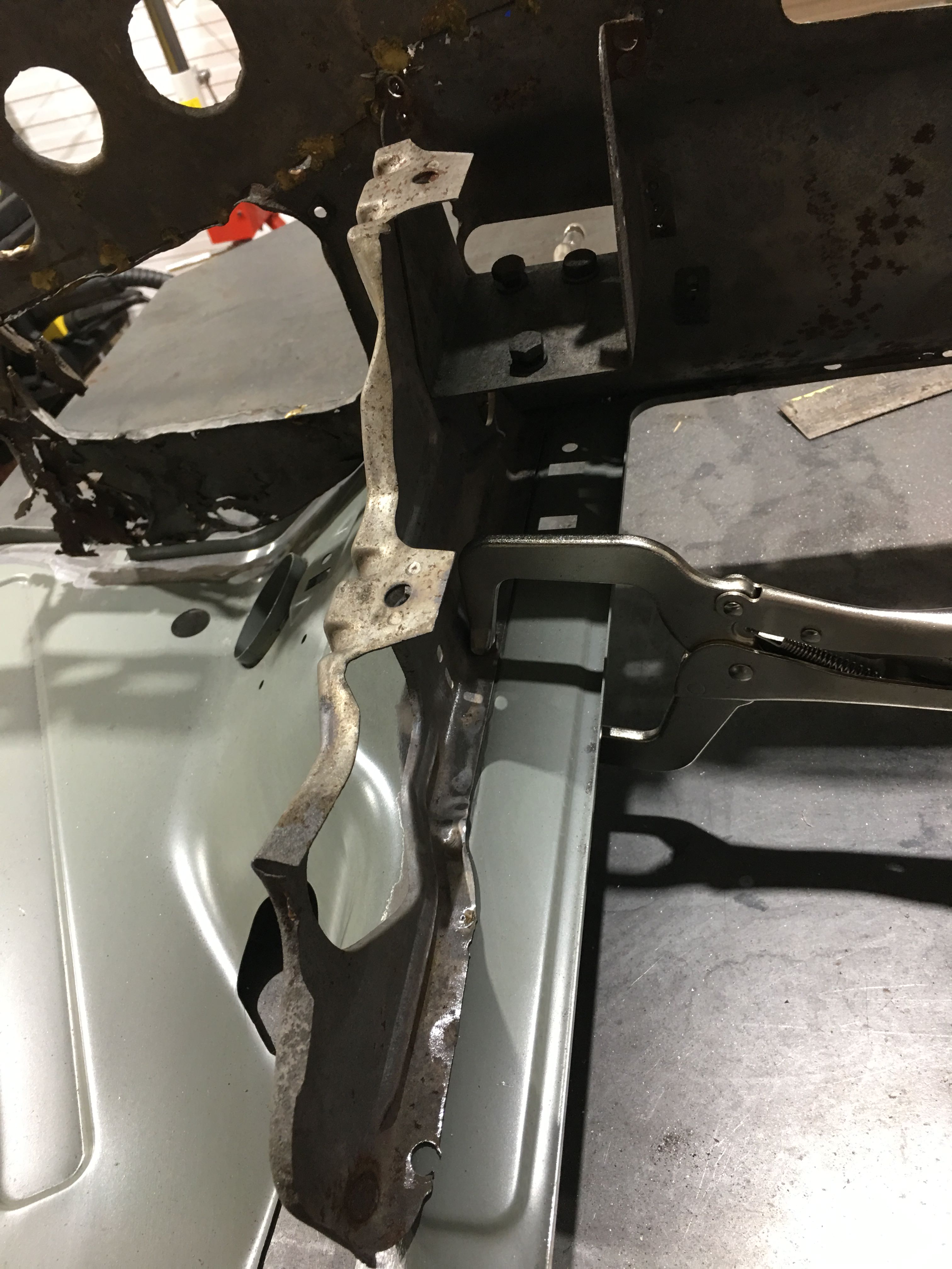
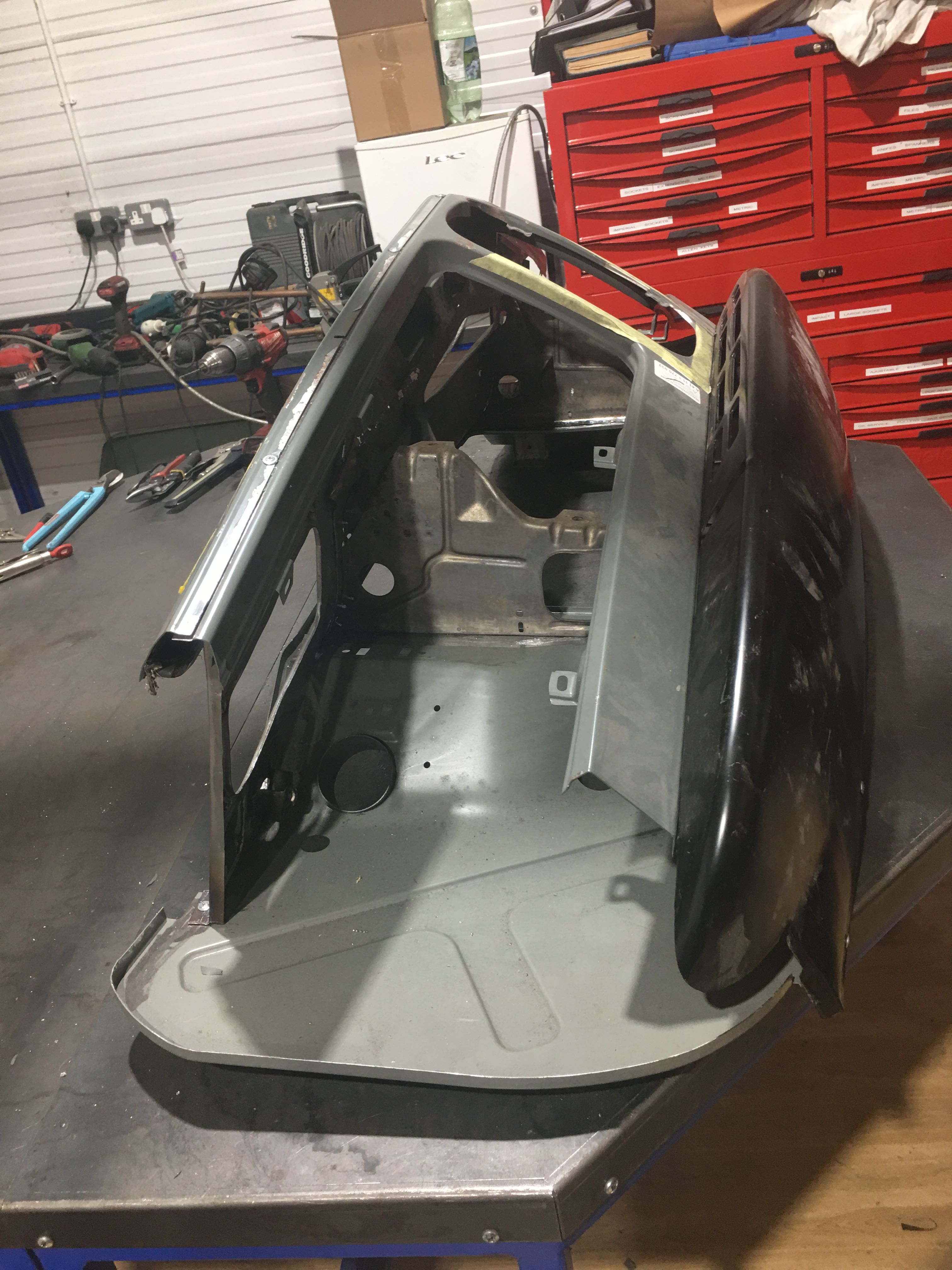
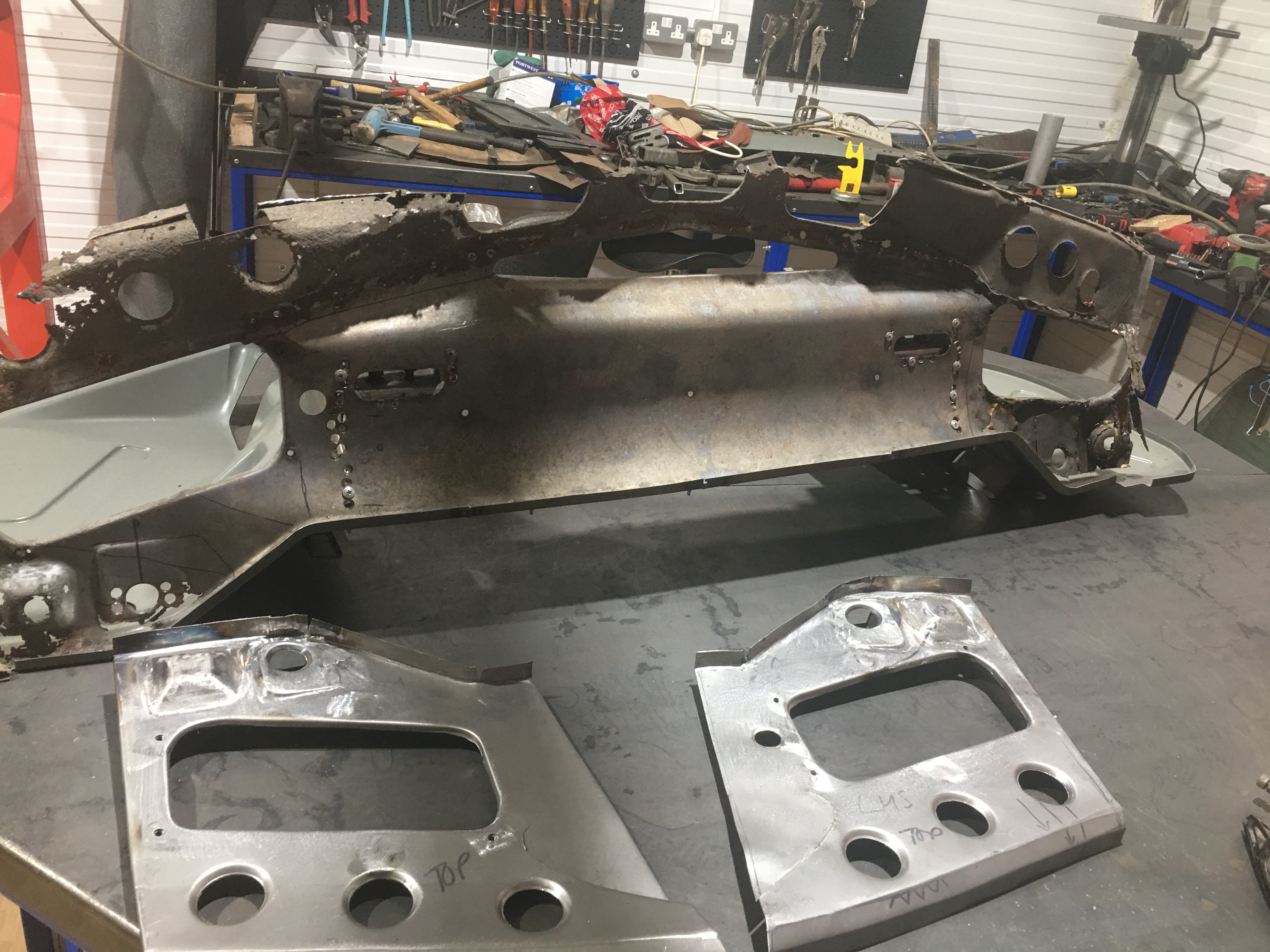
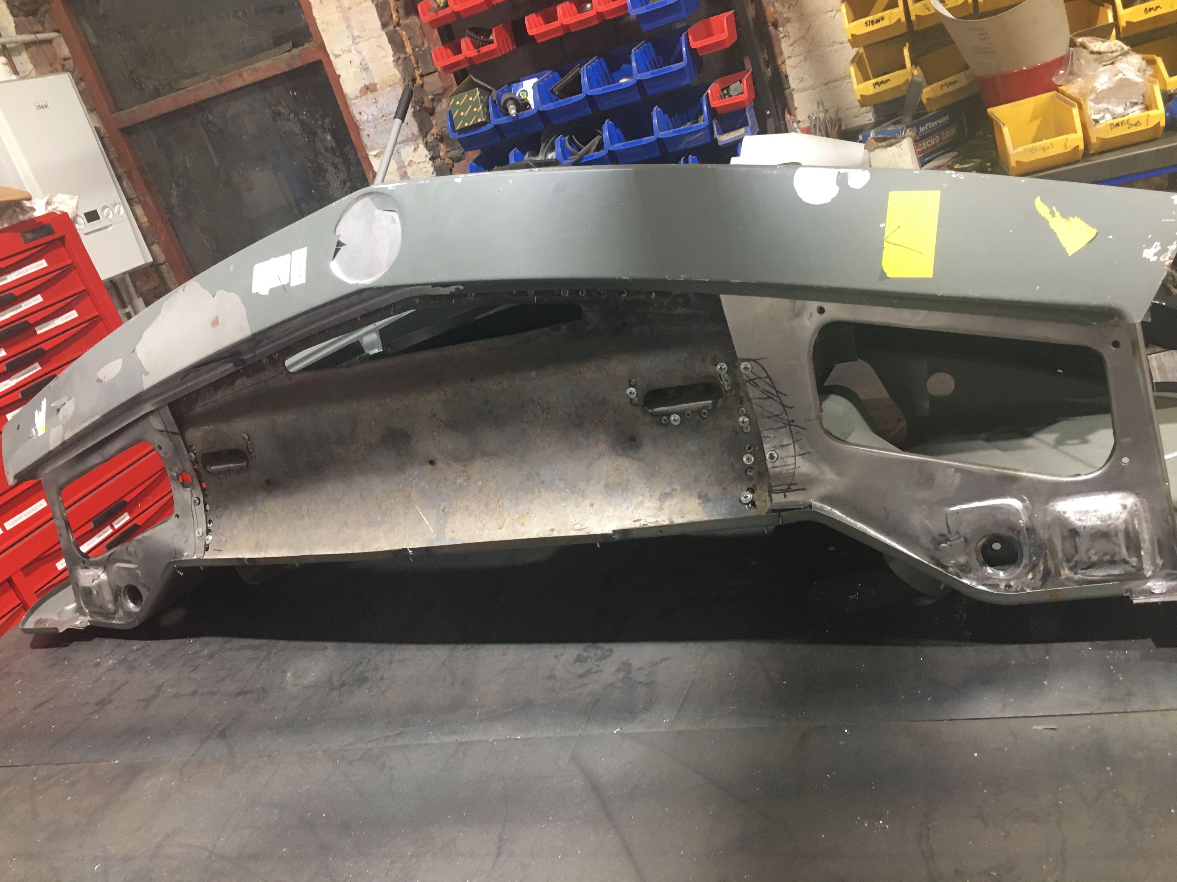
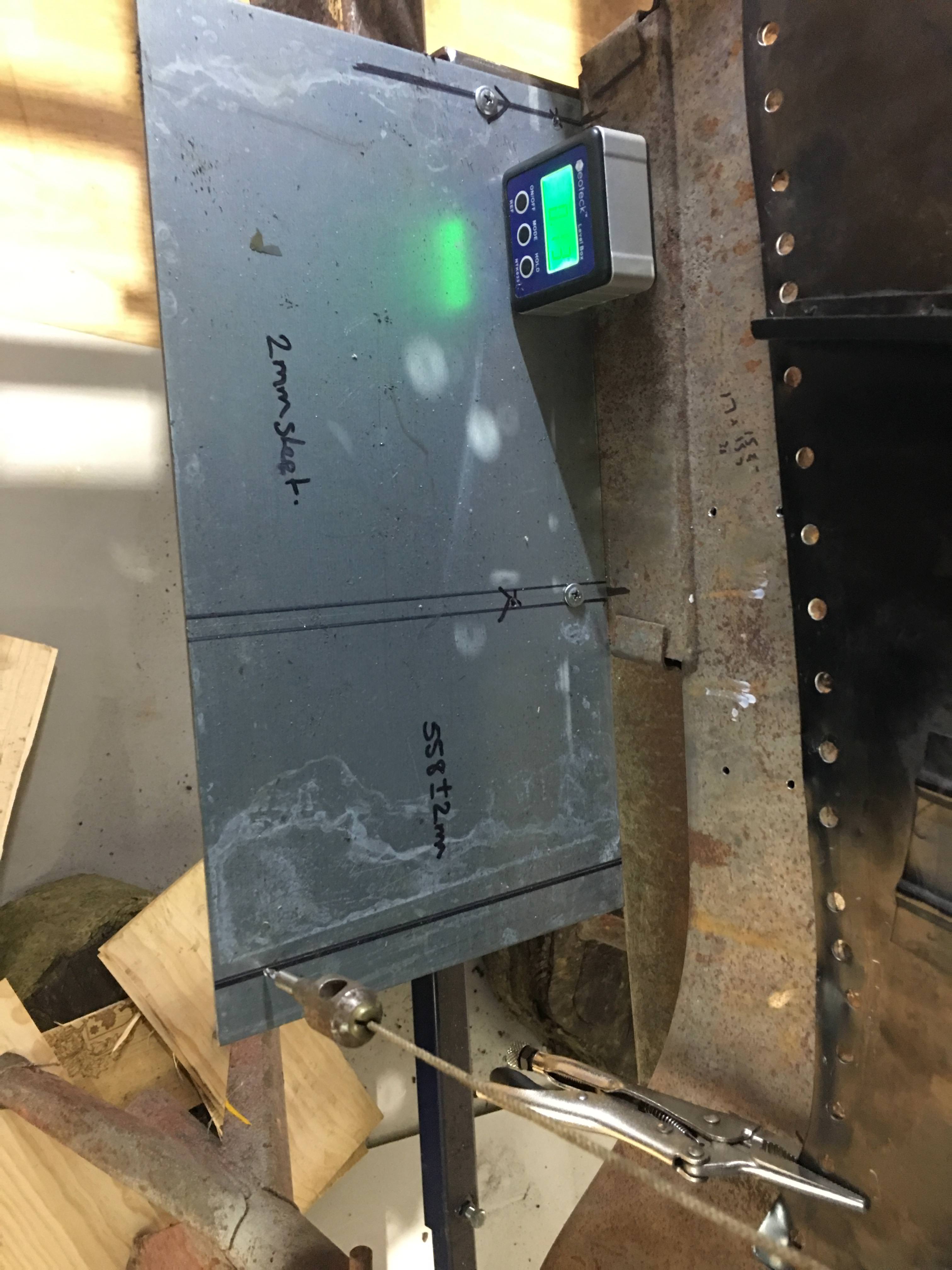
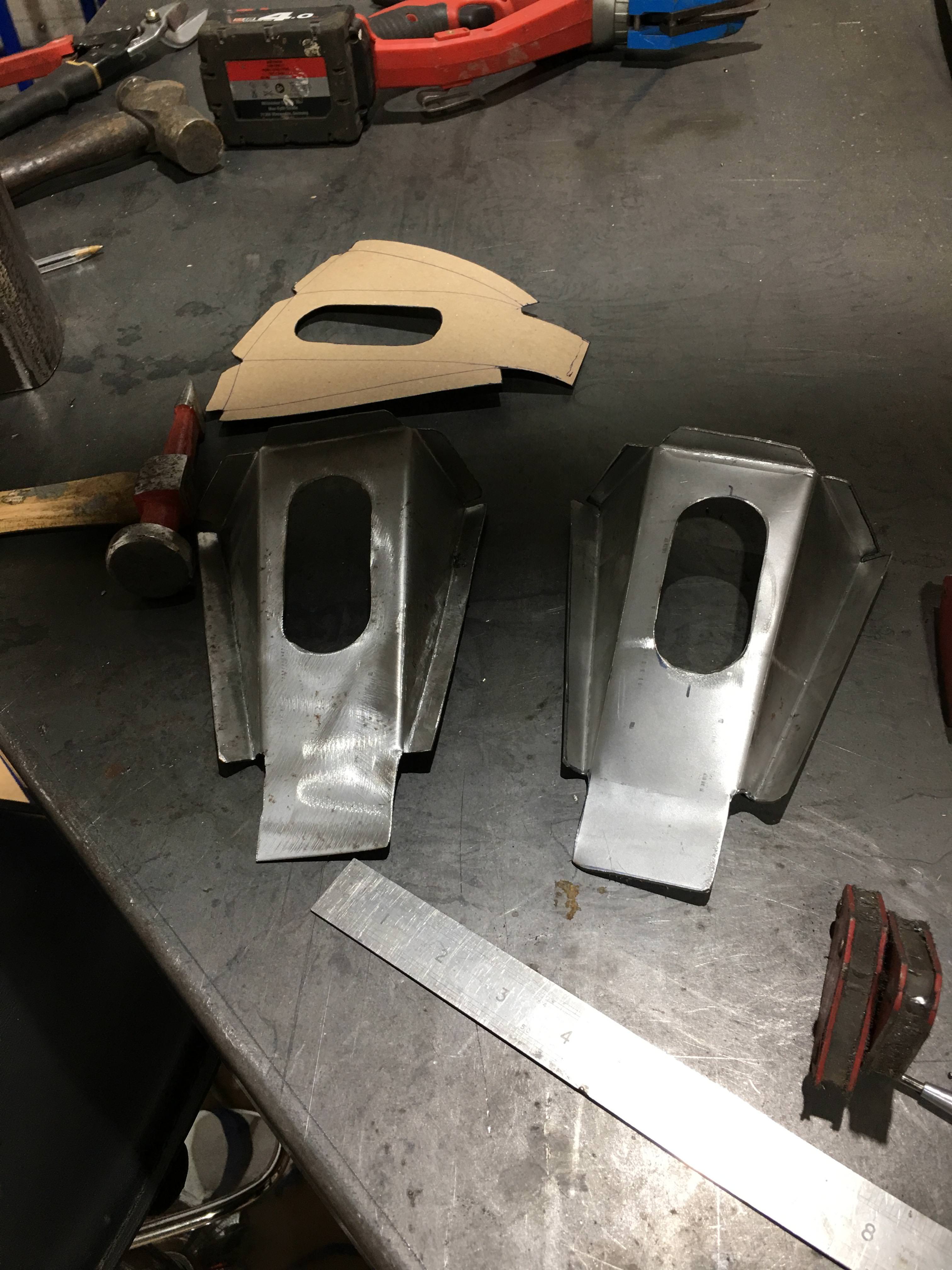
I have made and welded in the 1st section for bottom together with the radiator mounts, and now as it’s a stable section I have screwed all the panels together to trail fit.

Just as well, it all screwed together quite well, and with a mixture of original BMW parts and repro parts there was no need of a tapping stick to re align the panels.

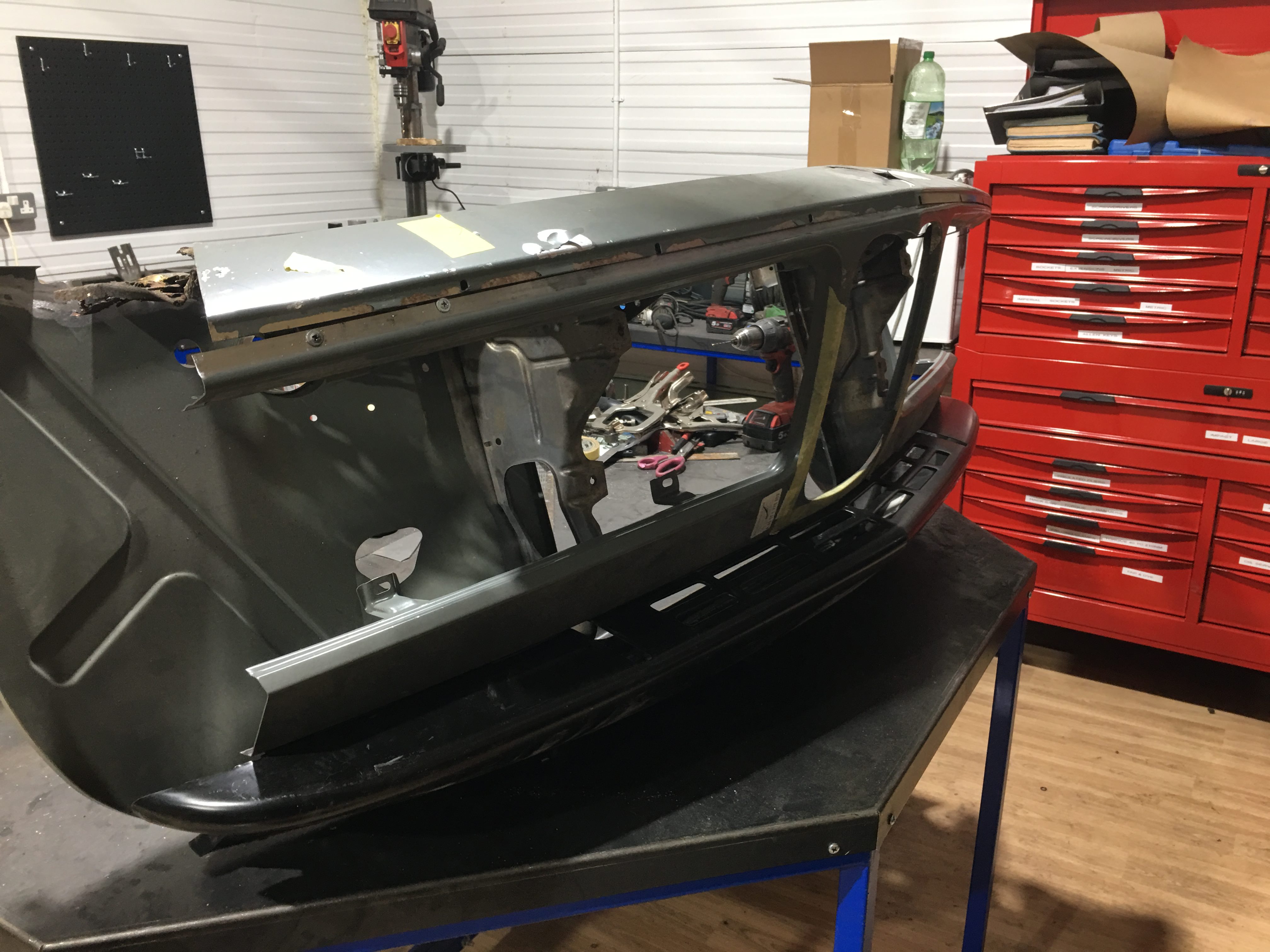
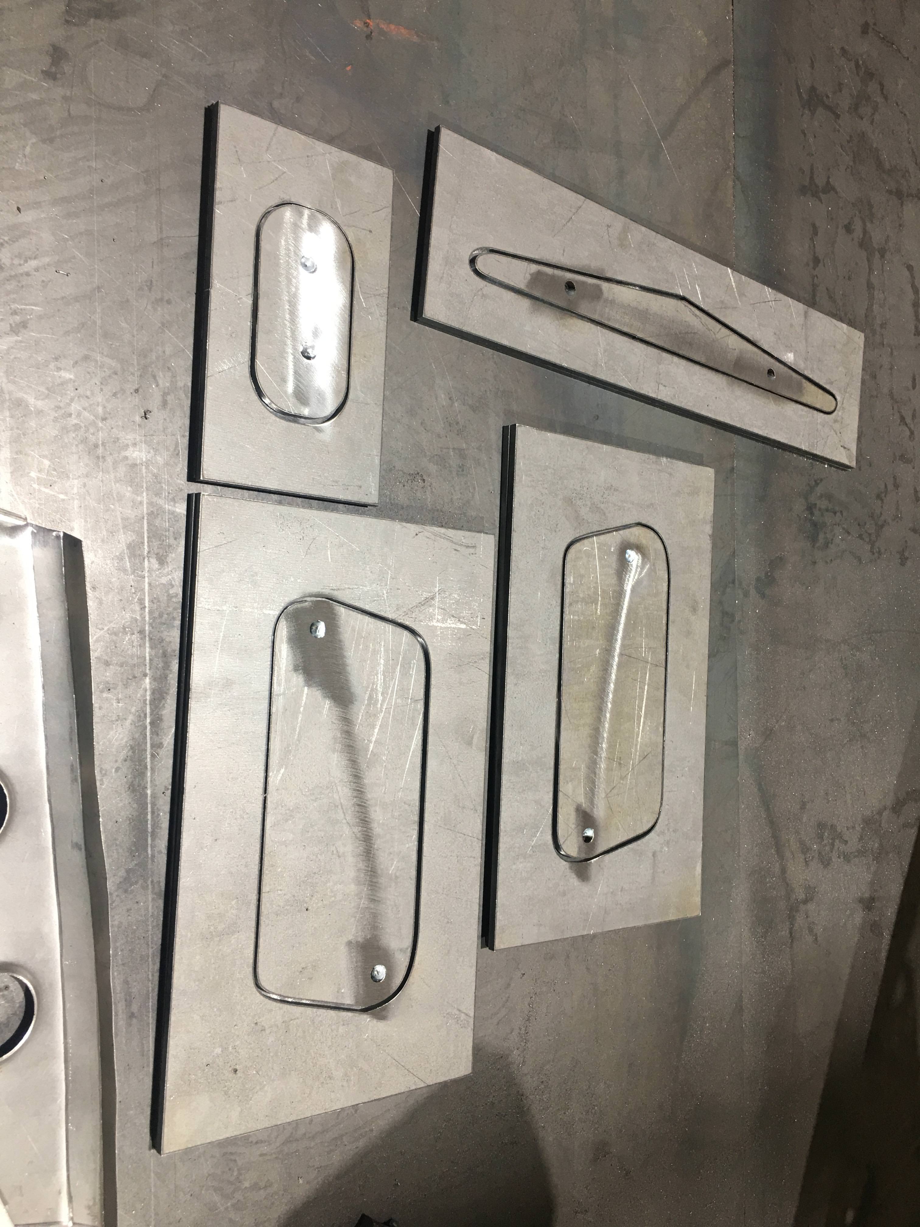
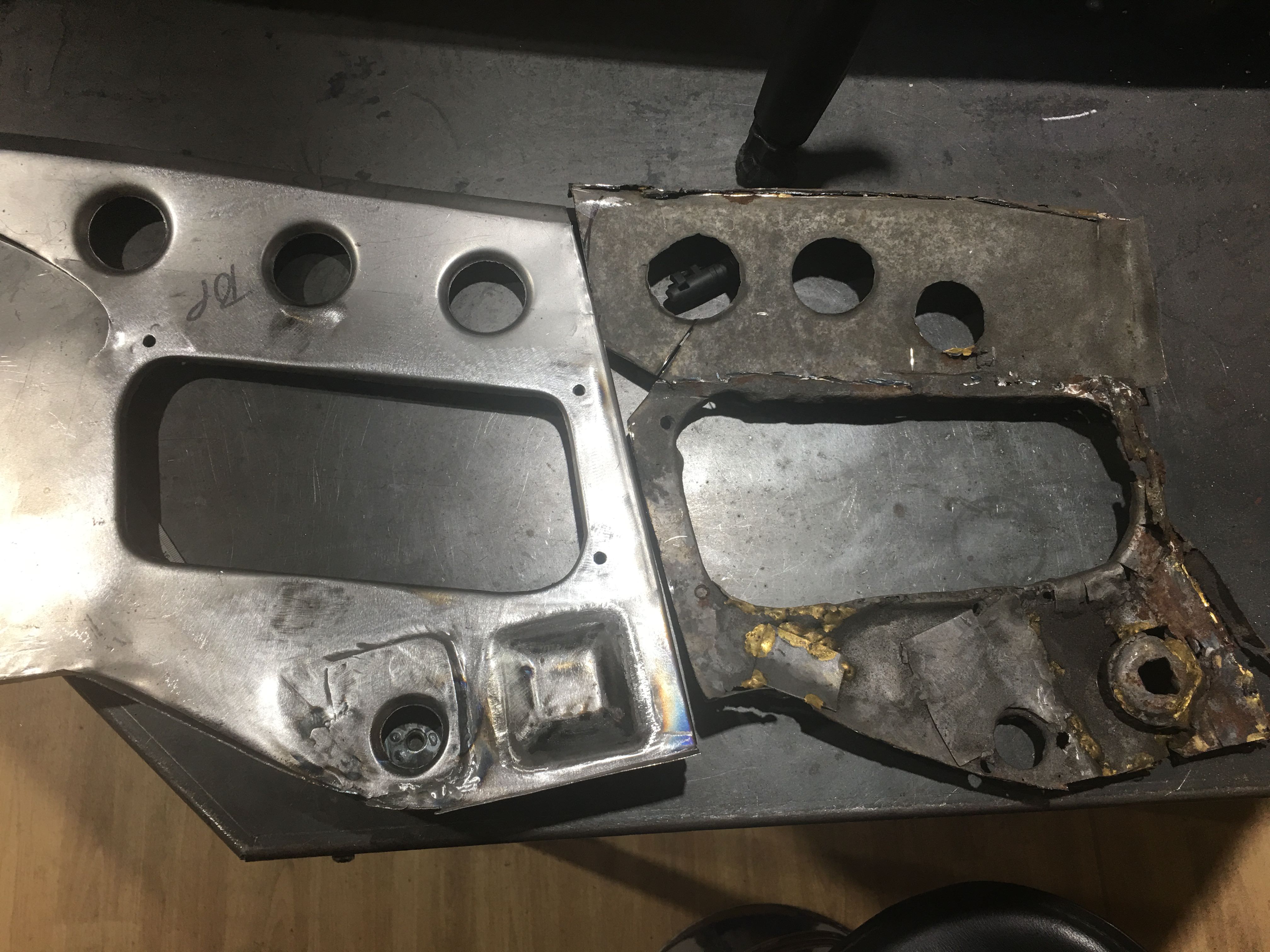
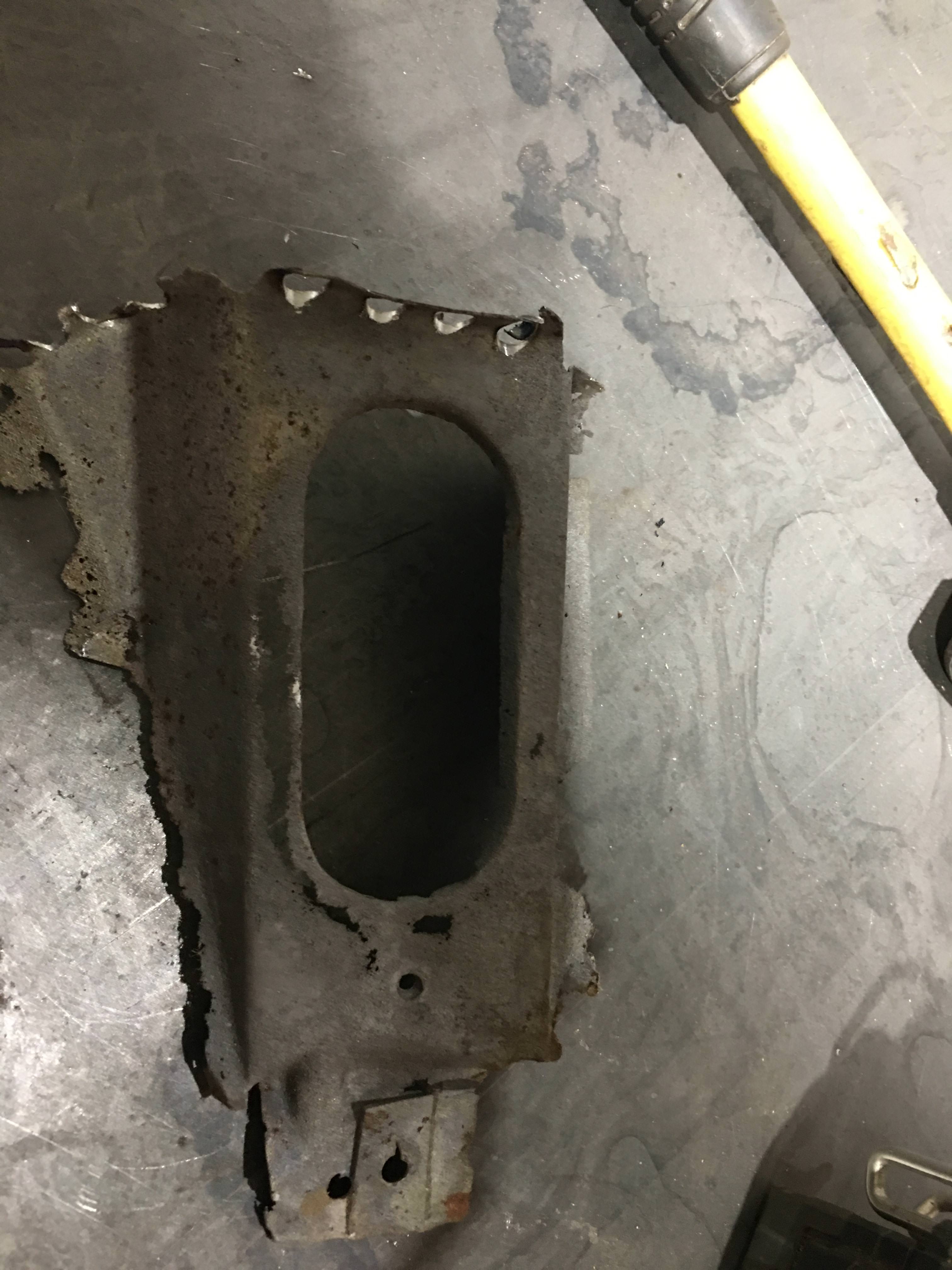
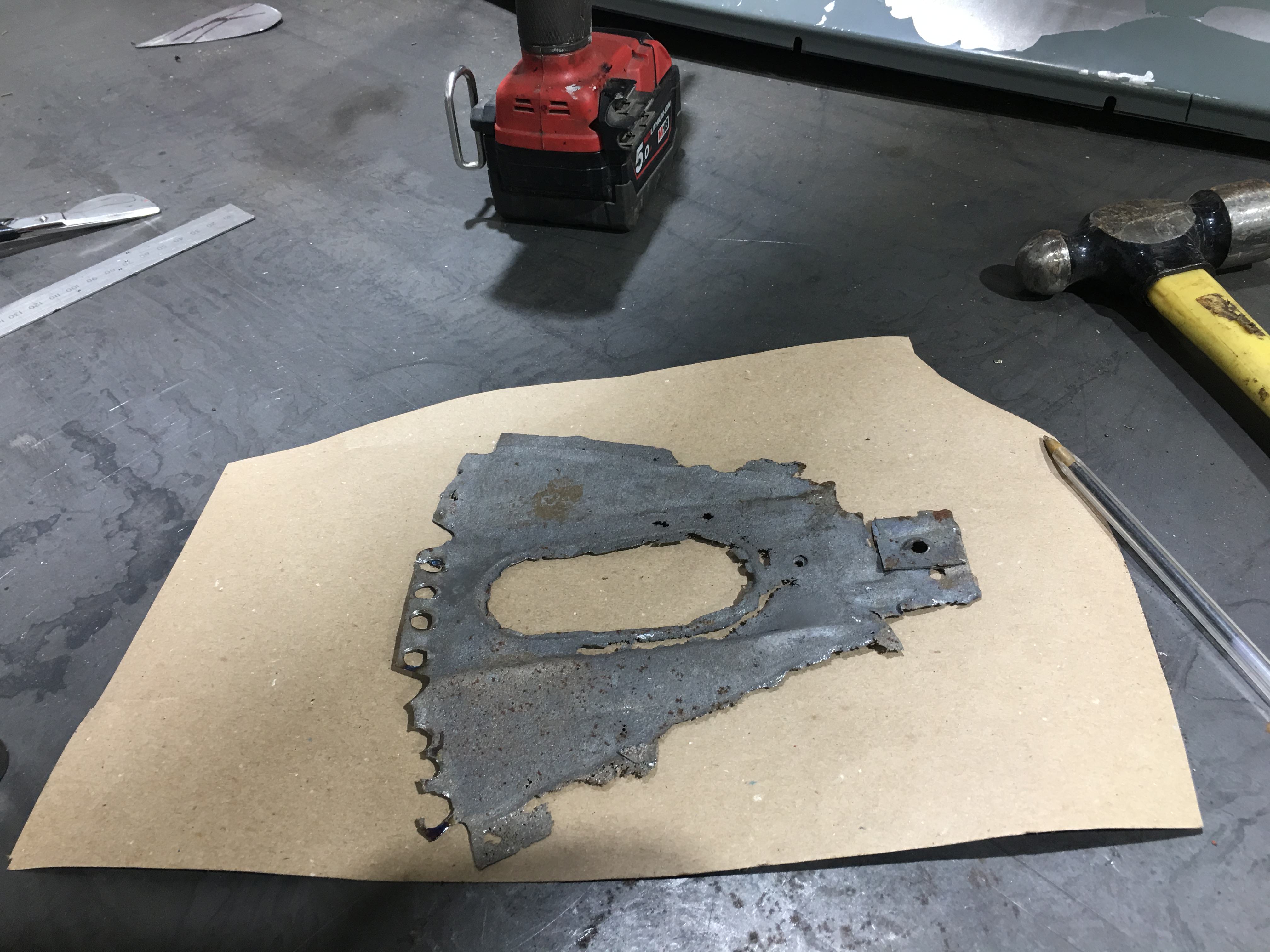
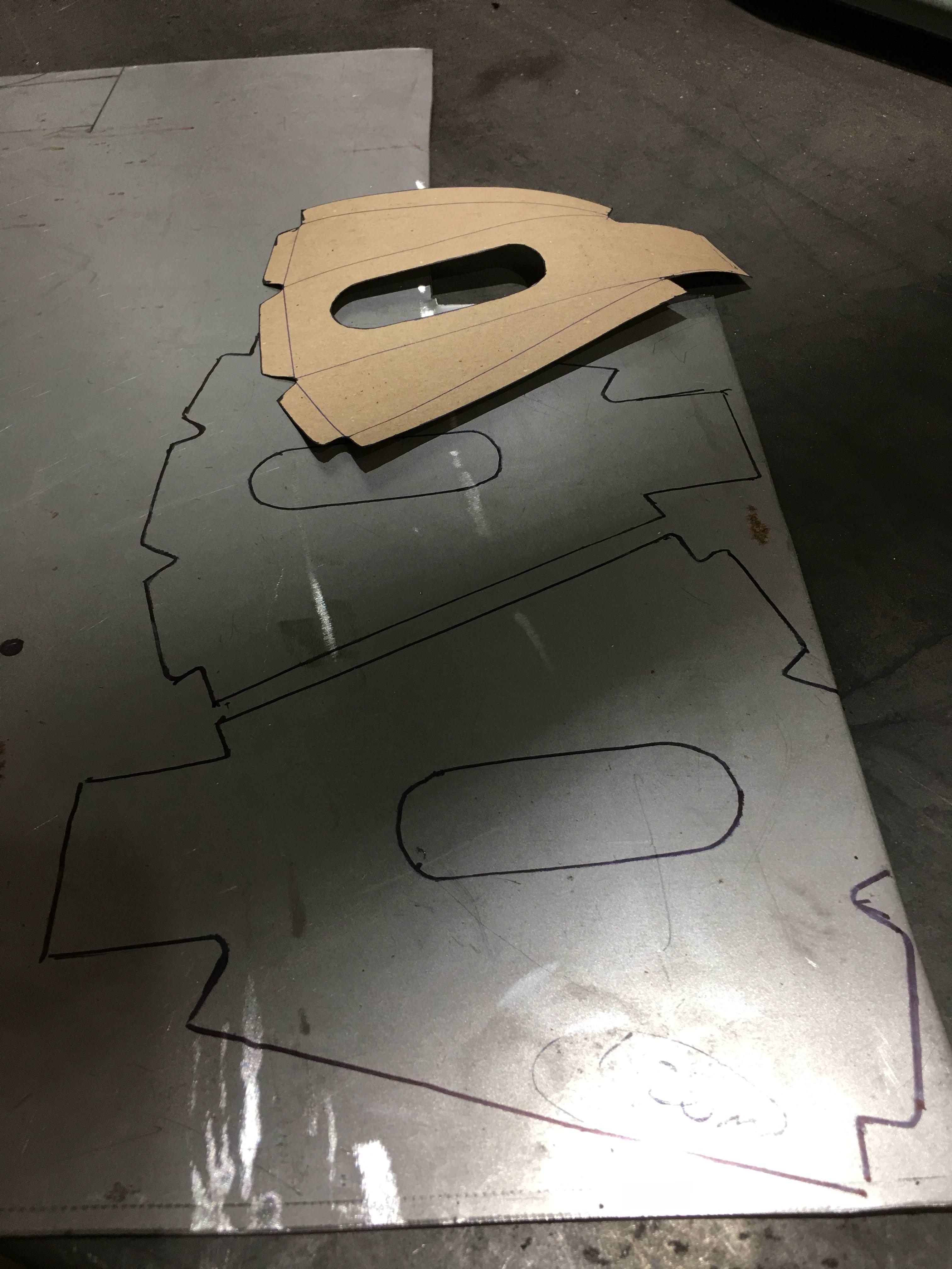
With it all screwed together I can now make a template of the last section that strengthens the bottom panel that welds to the new section I have made. I have no clue as to what this panel is called, maybe its called –the radiator scuttle lower reinforcement support section?????

I think I’m only a few nights from completing the nose now!

wFnt2qh.jpg

iykBLrg.jpg

mecuuNH.jpg
 

Marc-M

Well-Known Member
Messages
377
Reaction score
311
Location
Preston - Lancashire-UK
Yesterday my pressing parts turned up for the bonnet shut panel (again I don’t know what its really called)

All made out of 5mm steel and cut out to the same sizes as the original apertures give or take a few mm! these should make the repair panels look a bit more factory!

I could have used a hammer and dolly to do it but wanted to have a go this way, as its a bit more fun trying stuff out.

Surprisingly they did not cost that much – found a local company who does this a lot, and they CAD it out and cut them out for me for a small fee.

After plug welding on the base plates to the male sections ( I did this to stop the thin steel from warping), my method of compresing the shapes into the panels was to simply use 4 bolts aligned through and an impact gun to clamp the upper and lower plates.

The results (I forgot to take picture but will tonight) are really good, so it was a worthwhile exercise – I could now go into production with this tooling!

eil6YnN.jpg
 

autokunst

Well-Known Member
Site Donor $$
Messages
3,606
Reaction score
2,618
Location
Milwaukee, WI
Yesterday my pressing parts turned up for the bonnet shut panel (again I don’t know what its really called)

All made out of 5mm steel and cut out to the same sizes as the original apertures give or take a few mm! these should make the repair panels look a bit more factory!

I could have used a hammer and dolly to do it but wanted to have a go this way, as its a bit more fun trying stuff out.

Surprisingly they did not cost that much – found a local company who does this a lot, and they CAD it out and cut them out for me for a small fee.

After plug welding on the base plates to the male sections ( I did this to stop the thin steel from warping), my method of compresing the shapes into the panels was to simply use 4 bolts aligned through and an impact gun to clamp the upper and lower plates.

The results (I forgot to take picture but will tonight) are really good, so it was a worthwhile exercise – I could now go into production with this tooling!

eil6YnN.jpg
Man, I love this forum!
 

Marc-M

Well-Known Member
Messages
377
Reaction score
311
Location
Preston - Lancashire-UK
GTK09K3.jpg

I have finally started fitting the two ends into the existing bonnet shut panel.

There is quite a bit of curve shape needed to match to the existing panel, and I have managed to get it something like using the planishing hammer, but still needs a bit more work.

Screwed the two repair ends temporarily in place So I could build up the whole of the nose cone to check it all goes together!

With the grill/ light front panel screwed in place, this now gives me something to follow with regards to the bonnet shut panel as the middle section (well all of it really) was so rotted out.

Now I have something clear to follow, and can start making and pressing out panels for that section next week

The good news so far is, all the parts are slotting together very well and only small adjustments are required.

I will not be welding the valance and the front grill/light surround to the nose until I start building the car up – but will leave then screwed in place just to give it a bit of strength.

u4L5nYT.jpg

Old and new - In some places I have been a little bit over zealous with the grinder and gouged the steel – but my painter can deal with at as I can’t be bothered to make some more end panels – there has been quite a lot of processes to make them and am not in any mood to start over again.
H56jLxf.jpg

If you look at the front of the panel - you will see that I have nothing to follow! - so had to build up the whole section .
kBXOLpa.jpg


All screwed together - not for the first time!
 

Marc-M

Well-Known Member
Messages
377
Reaction score
311
Location
Preston - Lancashire-UK
The last week or so I’ve been trial fitting the two inner wings.

I have been lucky and managed to buy an old new stock RHS inner wing (a beige paint) that was made in 1982.

The LHS was still available direct from BMW. (black paint)

First, I must point out that the construction of the old 1982 inner wing is of a much better pressing.

When offered up, the old new stock simply dropped into place and only needed a little tweaking.

The new part took a good few nights of tweaking to get into the right place, I had to take a few breaks as I was ready to smash it up into little bits…….

To get the inner wings into the correct place I marked the dimensions (taken from the work shop manual) on a steel plate and mounted it level to the bottom of the front crossmember mounts.

I also quickly made up a blank with a small hole drilled into the centre to be bolted into the top of the suspension strut, the small hole is for dropping a plumb line through.

Looking at the pictures below you can see I have used my digital inclinometer (a great thing to have) to get the car level (I could not get better than 0.02 of a degree!).

The plum line from the top centre of strut is now within a mm of the line scribed into the steel plate, and that according to the workshop manual is within tolerance, the distance to the top of the suspension turret is 0.557mm, the correct dimension should be 0.558 plus or minus 2mm and that is in tolerance.

Now it’s pretty much fitted and I will screw it on temporarily, as I bet when I fit the nose cone it will throw everything off!
kepIHHO.jpg

COqBj4R.jpg

PNwh3mB.jpg


Made a few bits as well for the nose cone – 2 mounting brackets
6BJPSM4.jpg

5X0fjmz.jpg

1MlBcXX.jpg

j5DeFnV.jpg
 

Marco 54

Well-Known Member
Site Donor $
Messages
242
Reaction score
150
Location
Merseyside
Morning Marc

I'm sure I would have no idea how to do what you do.
Very impressive and inspirational work indeed.
Whatever the problem you find a solution - hats off to you!!!
 

mr bump

Well-Known Member
Messages
604
Reaction score
107
Location
nottingham, UK
Brilliant thread Marc, always a pleasure to see a craftsman at work. How did you create the X shape press in the headlight inspection panel? I want to make 2 new ones and want to get the X spot on.
 

pat cooks

Well-Known Member
Messages
220
Reaction score
92
Location
essex
I may have a pair of original steel access panels left, will look if you are interested, they are missing from my CSiL, were they alloy? I have kept a pair of steel but now have doubts.........
 

eriknetherlands

Moderator
Site Donor
Messages
2,697
Reaction score
1,929
Location
Netherlands, Eindhoven area
I made a hammer form from 10 mm thick steel. A pressing tool would be better, but with some hammering skills it works. Carefully measured the original up, cut some steel strips, rounded of the corners, and welded it together. that was one evening. then another to actually hammer form the part. I'm not sure if still have the form. If I find it i'll update with a picture.
 

adawil2002

Well-Known Member
Site Donor $$
Messages
5,183
Reaction score
3,045
Location
Brunswick, Maine
Brilliant thread Marc, always a pleasure to see a craftsman at work. How did you create the X shape press in the headlight inspection panel? I want to make 2 new ones and want to get the X spot on.

Those panels are available from Jaymic.com they are listed as out of stock so you'll have to call.
 

Marc-M

Well-Known Member
Messages
377
Reaction score
311
Location
Preston - Lancashire-UK
Brilliant thread Marc, always a pleasure to see a craftsman at work. How did you create the X shape press in the headlight inspection panel? I want to make 2 new ones and want to get the X spot on.
The way I would do it - is to use the bead roller, and change one of the rollers for a skateboard wheel.
This allows you to run a bead over another and not destroy it.
I have not made them yet but have taken a card template off a CSL - i will make then as it easy, I can always run an extra set off for you... its not a big job if you have the right tools..

Have a look at this.. this guy has some great tips


mr bump

Well-Known Member
Messages
604
Reaction score
107
Location
nottingham, UK
Those panels are available from Jaymic.com they are listed as out of stock so you'll have to call.
I don't feel like walking around like a penguin so jaymic is a no go, plus after looking at the quality.of their carpet sets, I won't go near them.
 

Marc-M

Well-Known Member
Messages
377
Reaction score
311
Location
Preston - Lancashire-UK
The CSL has been on the back burner a while now as I’ve been working on another car.

I did lose a little love over it as its had been a hard slog but leaving it a while and now getting back to it I have found a new happiness with it…. and now its on to the finish!!!

Getting the front inner wings in the correct place has been fun.

They are now in the correct position, some of the check points are perfect and some are 1mm out – so its well within the factory tolerance.

Getting the inner wings in position was very interesting and time consuming.

Screwed it all up, and it now ready for welding once I dress the whole body up - I need to ensure everything is perfect before I weld.

Next was to get the outer sill section and wings on one side of the car– then the door.

This was done last night and again was quite a fiddle – but still needs work to get the gaps right.

My intention is to build the whole car up and hold all the panels in place with Tec screws and get the gaps right before I take it all to bits again and weld it all in its final position.

This is going to be a long job, the most important job.
IMG_4302.JPG


IMG_4296.JPG


Not that bad for a few hours work - gaps getting better - but still a long was from being perfect.....
Good to see the car ,looking like a car ( well one half anyway).... been a long time...
 

paul

Well-Known Member
Site Donor
Messages
321
Reaction score
305
Location
Australia, Queensland, Gold Coast
Hi Marc........good work...you're going about it the right way........check everything before you weld. Caution on how the car is supported on the rotisserie. My car the final gap check was done on it's suspension as things changed when taken off the rotisserie which was supporting the body each end.Yours looks to be supported more inboard where the suspension would connect. PS....tuner started my engine today (its first time since rebuild) it fired up second go. Sounds beautiful.
 

Marc-M

Well-Known Member
Messages
377
Reaction score
311
Location
Preston - Lancashire-UK
Hi Marc........good work...you're going about it the right way........check everything before you weld. Caution on how the car is supported on the rotisserie. My car the final gap check was done on it's suspension as things changed when taken off the rotisserie which was supporting the body each end.Yours looks to be supported more inboard where the suspension would connect. PS....tuner started my engine today (its first time since rebuild) it fired up second go. Sounds beautiful.
Good shout.... I did not think it would move being a monocoque - but I will do as you say. - all the cars I have done have been body/ chassis cars.
Will bang the panels on temp - then weld the inner sections as is - then will support body chassis from the mounts only - then do the outer panels.....

I would kill myself if I did all that work, only to find it moved when the jig was off...

Thanks

Marc
 

Marc-M

Well-Known Member
Messages
377
Reaction score
311
Location
Preston - Lancashire-UK
Last night banged on some more panels to the other side and the boot lid - first fit - and as you can see they are miles away....
Just to put bonnet ( hood) on and then see what is needed to juggle/cut , bend, build up... the panels.
Any how here are some picture to show how much work I have getting them right!!!


PHOTO-2019-08-22-21-14-47.jpg
PHOTO-2019-08-22-21-14-53.jpg
PHOTO-2019-08-22-21-15-00.jpg
PHOTO-2019-08-22-21-15-13.jpg
PHOTO-2019-08-22-21-15-21.jpg
 
Top