I'll look at diagrams and German description again too. And try and compare with my car.
You are using an out of date browser. It may not display this or other websites correctly.
You should upgrade or use an alternative browser.
You should upgrade or use an alternative browser.
D-Jetronic Rebuild
- Thread starter 12doplumbing
- Start date
Bwana
Well-Known Member
OK, here's the diagram in my Blue Books. We verified it while troubleshooting the problem we had with the ECU a little while back. I've hand written in the apparent 4 sets of FI outputs and the two pins (21 & 22) that need voltage to the timing points for correct operation. The timing points are drawn incorrectly as compared to the actual points mechinism. As I mentioned, it looks like this is a modified setup from a four cylinder to a six cylinder. Yours looks like some sort of paired sets of three. You can copy and save this picture then enlarge it off forum to improve the viewing detail.
I should probably compare this to the firing order to see what happend to the "wasted" FI shot.
Any true D-Jet experts out there to sort this out?
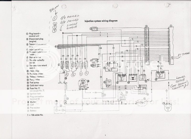
Edit: I just checked the drawing you posted and looked at my blue books again. It appears both the D-Jet MAP (item #10 in this diagram) and whatever the other systems (K-Jet air flow sensor) are both covered in the blue books so be sure to figure out which you have. You can't tell any wiring detail from the picture you posted.
I should probably compare this to the firing order to see what happend to the "wasted" FI shot.
Any true D-Jet experts out there to sort this out?
Edit: I just checked the drawing you posted and looked at my blue books again. It appears both the D-Jet MAP (item #10 in this diagram) and whatever the other systems (K-Jet air flow sensor) are both covered in the blue books so be sure to figure out which you have. You can't tell any wiring detail from the picture you posted.
Last edited:
Bwana
Well-Known Member
Going nuts with the "edit", sorry. Yours "looks" like a MAP system from the hose that goes up by the firewall.
Why not use the schematic on this site?
http://www.e9coupe.com/tech/autobooks/appendix/autobooks_manual_160.htm
http://www.e9coupe.com/tech/autobooks/appendix/autobooks_manual_160.htm
12doplumbing
Well-Known Member
Bwana: your schematic is the best, since it has the numbers of the factory wires. Thank you. Sfdon: is there a second page with a key?
Twistinglane, Chris, your scheme doesn't seem to match; my harness feeds/originates from Cyl 1 side.
Anyway, I think I've got it. I found the temp sensor #13, and on Cyl 3-4-5-6 I found one of the numbers still visible on the pairings. So with Bwana's schematic I can see which is ground and which is positive. Cyl 1&2 I'm pretty certain which pairing goes to 1 and which to 2, just not sure which will be ground.
***Then the kicker: my new wire lead clips from Fuel Injection can attach to the injector in either direction -- but that doesn't matter. What I'm lost on: which side of the injector is positive? Left or right?


Thanks Bwana, Don. The blue book version is clearer. The one I posted is Bosch's diagram for d-jet BMW also (hopefully they are consistent!) What I missed before is that wires 26 and 27 join to form wire 3 to feed into ECU. And similarly wires 28 and 29 join to form wire 5 to ECU. Thus as you point out only 4 wires reach ECU from injectors.
12do: I can see your point of confusion. Having just played with some original spare parts, I see the two wire connectors can fit on injectors either way. Hopefully, as seems reasonable, that is a design feature and direction doesn't matter. For what it's worth, the diagram I posted shows the grounds on the left if you look down on injectors from behind.
12do: I can see your point of confusion. Having just played with some original spare parts, I see the two wire connectors can fit on injectors either way. Hopefully, as seems reasonable, that is a design feature and direction doesn't matter. For what it's worth, the diagram I posted shows the grounds on the left if you look down on injectors from behind.
Bwana
Well-Known Member
Why not use the schematic on this site?
http://www.e9coupe.com/tech/autobooks/appendix/autobooks_manual_160.htm
Because then it's hard for him to see what I've scribbled on my monitor! :lol:
12doplumbing
Well-Known Member
Twistinglane: "looking down on the ejectors from behind"? Looking from passenger side, over the valve cover and under the intake, my injectors have the wire feeds facing me and the short rubber fuel lines behind. Are you saying the ground side is the left from this angle?
And I have all but cylinder 1 identified for positive and negative. Surely there is a way to check with a meter which is positive and negative. If anyone has a thread lead, I'd appreciate it. I'm close...
And I have all but cylinder 1 identified for positive and negative. Surely there is a way to check with a meter which is positive and negative. If anyone has a thread lead, I'd appreciate it. I'm close...
In my last post, I was just trying to describe positioning of wires that i saw in diagram from post #57 below. However, as you note the injector plugs seem to fit both ways. And old injector I'm looking at ( a 015) shows no polarity. A bit of Google search seems to confirm polarity doesn't matter. So I'm going to say which way you inset plug into injector doesn't matter... Someone chime in if there is something else to be said here.
Last edited:
12doplumbing
Well-Known Member
Okay! Got it all connected; injectors wired with, hopefully, all the grounds in proper order. I just used left side as ground when connecting to injectors.
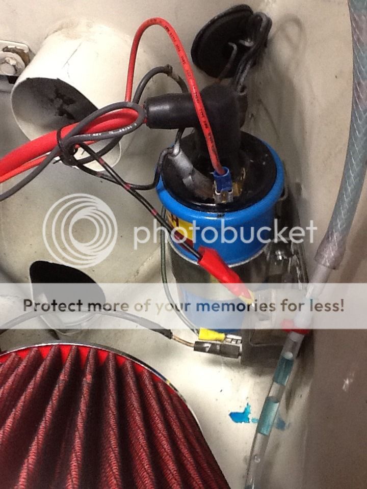
PROBLEM: can't figure out why my ballast resistor is overheating now; glowing and smoking every time I turn ignition on... Help, anyone? I replaced the starter since the last time I started it, so I could have screwed up those connections... But it did turn over and even ran a second before stalling (but that's probably due to all the air and lack of fuel in the system). I swapped the Pertronics connection from the bottom of the ballast back up to the positive terminal of the coil. Other than this, the green wire coming from in front of the radiator support is still hooked up to the bottom of the resistor, along with the white wire going (?). The black and red spotted wire connected to the top of the ballast goes to the positive side of the coil and is jumped with the same colored wire which follows the green one in front of the radiator support. I didn't touch any of these connections at the coil since it ran last, so it has to be on the other end of these; like where that white one down below connects...
 [/URL]

PROBLEM: can't figure out why my ballast resistor is overheating now; glowing and smoking every time I turn ignition on... Help, anyone? I replaced the starter since the last time I started it, so I could have screwed up those connections... But it did turn over and even ran a second before stalling (but that's probably due to all the air and lack of fuel in the system). I swapped the Pertronics connection from the bottom of the ballast back up to the positive terminal of the coil. Other than this, the green wire coming from in front of the radiator support is still hooked up to the bottom of the resistor, along with the white wire going (?). The black and red spotted wire connected to the top of the ballast goes to the positive side of the coil and is jumped with the same colored wire which follows the green one in front of the radiator support. I didn't touch any of these connections at the coil since it ran last, so it has to be on the other end of these; like where that white one down below connects...

12doplumbing
Well-Known Member
The white one is labeled 41 -- and I see it comes from the main relay... The green one is labeled "On" on Twistinglane's diagram....
The only real variable/questions concerning my wiring were:
1) I added a ground wire from my distributor to a valve cover bolt (I disconnected it, and no difference)
2) Cylinder 1 injector leads was the only pairing I couldn't identify positive and ground side. If ground were hooked up to the right side, and all other cylinder grounds hooked up to left, could this be the cause?
You have a Blue coil, get rid of the resistor, you are reducing the voltage as the blue coil has an internal resistor. My resistor turned bright red once after I replaced my starter, it didn't have switched power terminal like the old one did so I hooked it up to the other terminal on starter and it had full power all the time and it overheated it, not good!
12doplumbing
Well-Known Member
Okay -- following instructions now (btw, found this thread: http://www.e9coupe.com/forum/showthread.php?t=2376&highlight=Ballast+glowing
They had same issue, but chose to put the old starter back in...)
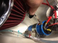
So I'm putting the white (#41) and the green on the positive side of the coil? Along with the Pertronics and black/red-spotted too? Create a fourth paddle (see photo)?
Appreciate your help Chris...
They had same issue, but chose to put the old starter back in...)
So I'm putting the white (#41) and the green on the positive side of the coil? Along with the Pertronics and black/red-spotted too? Create a fourth paddle (see photo)?
Appreciate your help Chris...
Attachments
12doplumbing
Well-Known Member
I don't think that black/red-spotted wire is supposed to be hooked up, is it? It feels real hot... after I turned it over...
12doplumbing
Well-Known Member
What's this plug for?
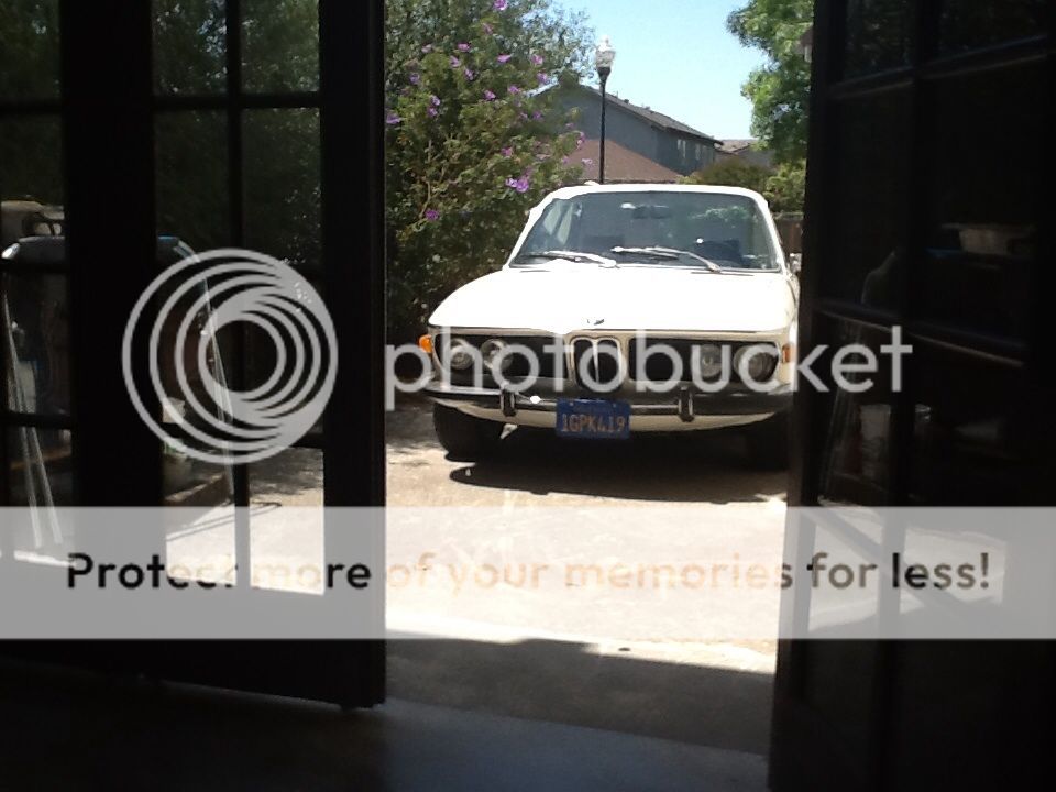
She's running!
Smoking like a freight train...

But no smoke at coil this time Chris - yesss
I just left that black/red-spotted wire hanging... Kind of like my wife on this Saturday...
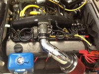
This gauge is telling me 29lbs (plumbed it in to check if stuttering problem could've related to pressure...)

I found this empty plug under the relays in front of the battery...

I'm going driving!
She's running!
Smoking like a freight train...

But no smoke at coil this time Chris - yesss

I just left that black/red-spotted wire hanging... Kind of like my wife on this Saturday...
This gauge is telling me 29lbs (plumbed it in to check if stuttering problem could've related to pressure...)

I found this empty plug under the relays in front of the battery...

I'm going driving!
That plug should be for fog lights, all harnesses have them.
12doplumbing
Well-Known Member
Ok. Thanks.
Oh, and Chris: I'm almost done with protecting my wire connections at the injectors, but I let her really warm up; new radiator, t-stat, hoses, fuel regulator, filter, plugs, wires, coil, injector rebuild, fuel lines -- all in hopes of curing that miss/stutter above 3500 rpms, and the dieseling when shutting her down. This thread goes so far back in my learning curve... I really hated the dieseling, and when I just shut her down NO BLEEPING DIESELING
Yesss
Thanks for all the help.
I'll post on the stuttering issue after I get back from a drive....
Attachments
12doplumbing
Well-Known Member
Test drive...
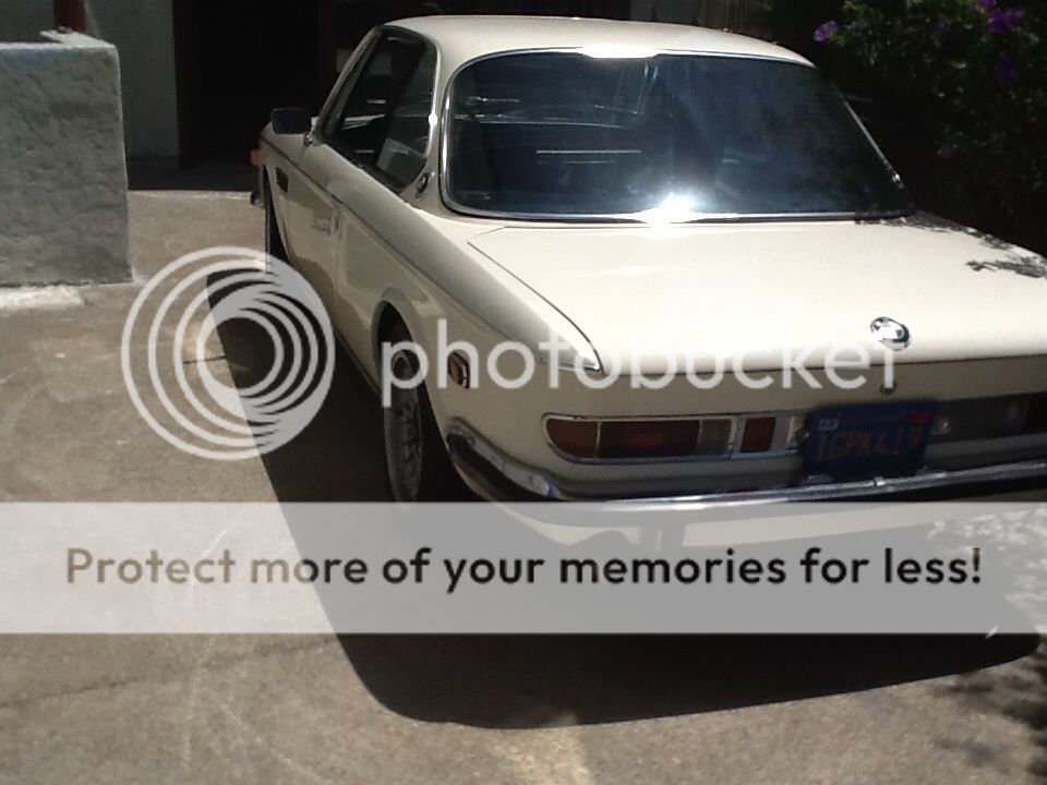

Okay, so short test drive results: NADA; loud and clear: NADA DAMNED STUTTER!
She sounds so much tighter and more responsive than when I got her. That felt great. I feel like I earned the right... To drive her, of course.
I'm not quite totally satisfied, though; when I shut her down this time, there was a tiny bit of dieseling.
So now off to read up on how to check timing and what other items haven't been checked...
More after Mother's Day
12doplumbing
Well-Known Member
Ok, so I spoke too soon; I'm having issues still. The dieseling isn't an issue anymore, but I'm still having fuel delivery or stuttering hesitation issues.
Pamp, another member, suggested I install another ground from the fuel pump ground location at the ECU:

To the negative terminal of the battery (I did, via the trunk, adding additional connection under a pump bolt):


I think I've got to check on the temperature sensor, then maybe the fuel relay (?) - because it acts like I've got too small of a fuel line (and maybe I do?).
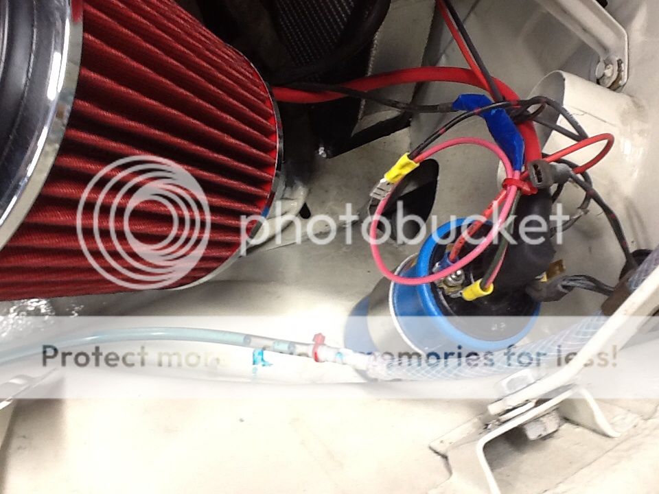
Also: I don't know what to do with wire #16, the black and red-spotted wire at the coil. Since I got rid of the resistor, I don't know what to do with this #16. This is before I removed the resistor:
The two other wires that were connected at the resistor, those were supposed to goto the positive side of the coil -- I hope!

The red wire shown with the loop is the white BMW wire. Then there is a dark green one connected to the same side which goes through the radiator support, and the third positive side coil wire, another red, goes to my Pertronics in the distributor. The #16 black and red-spotted wire starts to smoke and melt when I leave connected to this positive side, so on my test drive I just left #16 undone. This leads me to believe I've got the white wire and dark green wire, possibly, on the wrong side of the coil as well. Maybe I'm supposed to connect #16 to the white and dark green? I'm confused. Can't tell how to do this from my new handy indestructible cheat sheet. Think one goes to the "Speed Relay" and the other to the ECU:

Anyone - help, please. Symptoms again: feels like she's never quite warmed up, or is starved for fuel a bit, and hesitates or stutters. I left it in second gear and held her at 3500 rpms for quite some time without any stutter or "starvation" symptom -- before the new ground wire, I believe I experienced interruptions and stutters in this spot. So what to check first? All injectors are rebuilt, all wire leads new, coil new, plugs and plug wires new.
Pamp, another member, suggested I install another ground from the fuel pump ground location at the ECU:

To the negative terminal of the battery (I did, via the trunk, adding additional connection under a pump bolt):


I think I've got to check on the temperature sensor, then maybe the fuel relay (?) - because it acts like I've got too small of a fuel line (and maybe I do?).
Also: I don't know what to do with wire #16, the black and red-spotted wire at the coil. Since I got rid of the resistor, I don't know what to do with this #16. This is before I removed the resistor:

The two other wires that were connected at the resistor, those were supposed to goto the positive side of the coil -- I hope!

The red wire shown with the loop is the white BMW wire. Then there is a dark green one connected to the same side which goes through the radiator support, and the third positive side coil wire, another red, goes to my Pertronics in the distributor. The #16 black and red-spotted wire starts to smoke and melt when I leave connected to this positive side, so on my test drive I just left #16 undone. This leads me to believe I've got the white wire and dark green wire, possibly, on the wrong side of the coil as well. Maybe I'm supposed to connect #16 to the white and dark green? I'm confused. Can't tell how to do this from my new handy indestructible cheat sheet. Think one goes to the "Speed Relay" and the other to the ECU:

Anyone - help, please. Symptoms again: feels like she's never quite warmed up, or is starved for fuel a bit, and hesitates or stutters. I left it in second gear and held her at 3500 rpms for quite some time without any stutter or "starvation" symptom -- before the new ground wire, I believe I experienced interruptions and stutters in this spot. So what to check first? All injectors are rebuilt, all wire leads new, coil new, plugs and plug wires new.