Fixing that little rust spot...

eriknetherlands

Moderator
Site Donor
Messages
2,760
Reaction score
2,000
Location
Netherlands, Eindhoven area
Impressive and inspiring, as usual, Erik. How do you fend off the local car restoration enthusiasts that need a particular NLA part fabricated? ;)

I lend them the specific tools that I made... but they have to come over for coffee / beer and talk e9's for a whole evening in the garage, with the fireplace nicely keeping the winter cold out!
 

nosmonkey

In Rust We Trust
Site Donor
Messages
1,103
Reaction score
1,002
Location
London, UK
Fantastic work as always Erik, always a pleasure seeing the work you're doing done at such a high standard
 

eriknetherlands

Moderator
Site Donor
Messages
2,760
Reaction score
2,000
Location
Netherlands, Eindhoven area
Fitting Walloth replacement panel the last weeks.

After getting the W&N part cleaned, zinced and into rough shape, I saw that the curve from top to bottom doesn't 'flow' nicely. The 2 edges are flush, but over a length of about 10 cm /3 inch, there is a air gap that shouldn't be there. The gap is about 2mm at the widest point, enough to fit a thin paint stirring stick in there.

To know where I should strive for, I made a template out of 2 mm thick steel plate, using my NOS quarter panel as the reference.

Started out with a rough shape using a long shape-copying-thing ( the blue thing)
Copied that onto steel, and roughed it out.
Then I took a Sharpy and drew a thick black edge. This makes that you can see a scratch line better on the grey plate while grinding later.

Then placed the steel plate on the NOS panel and I traced the shape of the NOS panel into the Sharpie line. Take care to keep your scratch-line-device perfectly perpendicular to the length of the steel plate at all times. If you keep it perpendicular to the car's surface, then you end up with a line that is too wide where the panel goes around a curve.
Then accurately grinded the steel plate up to the scratch line.

Checking the resulting template to the NOS panels shows only 0,5 mm airgap at the most, enough for me.
 

Attachments

  • 20220422_112217.jpg
    20220422_112217.jpg
    274.6 KB · Views: 214
  • 20220422_112259.jpg
    20220422_112259.jpg
    249.7 KB · Views: 205
  • 20220422_111510.jpg
    20220422_111510.jpg
    301.6 KB · Views: 188
  • 20220422_113627.jpg
    20220422_113627.jpg
    262.1 KB · Views: 177
  • 20220422_120803.jpg
    20220422_120803.jpg
    225.9 KB · Views: 174
  • 20220422_120526.jpg
    20220422_120526.jpg
    320.3 KB · Views: 181
  • 20220422_122809.jpg
    20220422_122809.jpg
    261.6 KB · Views: 185
Last edited:

eriknetherlands

Moderator
Site Donor
Messages
2,760
Reaction score
2,000
Location
Netherlands, Eindhoven area
Most tricky part (for me) is getting the curve on the quarter panel from top to bottom just right after welding. Part of all this work that you see below is that I'm fearful that my hobby skills are going to shout "hack-job" from 20 feet away after paint.

The template I made in the post above worked quite ok, but if I used it 15 cm further to the rear on the car, it showed that it could not be used there; the shape is off.
So I made second template fitting a bit further to the rear.

I installed them in the car with these super strong 5 cm / 1.8 inch magnets . They are really fantastic, and keep the templates at a nice 90 angle to the car, while allowing them to reposition them with a light tap.

I also use them to hold panels while welding, but be careful: if they get hot, they loose their magnetism.

The second template showed also that right where I'm planning to but weld them, the edges tuck in about 3 mm (1/8 inch).

to counter this, I am considering to brace them from behind during welding. I'm just going to hope that it'll stay that shape during and after welding.
I tried to brace it into place by pushing the but weld edges from behind; looing at it, It does close the air gap nicely.
Sofar it is all dry fitting still.

Let's hope that by welding slowly and lots of cooling, that I can keep that shape.
 

Attachments

  • 20220423_173700.jpg
    20220423_173700.jpg
    254.1 KB · Views: 185
  • 20220423_173714.jpg
    20220423_173714.jpg
    235.9 KB · Views: 190
  • 20220424_105046.jpg
    20220424_105046.jpg
    273.4 KB · Views: 175
  • 20220424_105154.jpg
    20220424_105154.jpg
    218.9 KB · Views: 185
  • 20220424_105627.jpg
    20220424_105627.jpg
    170.7 KB · Views: 174
  • 20220424_111210.jpg
    20220424_111210.jpg
    271.2 KB · Views: 174
  • 20220424_111232.jpg
    20220424_111232.jpg
    175.2 KB · Views: 163
  • 20220424_111243.jpg
    20220424_111243.jpg
    180.3 KB · Views: 187
Last edited:

eriknetherlands

Moderator
Site Donor
Messages
2,760
Reaction score
2,000
Location
Netherlands, Eindhoven area
I am in constant awe of your metal fab skills and attention to details.
well, let's see if it works out like I hope!

I still need to fab some spotwelder arms to be able to spotweld the wheel arch; it requires a funny setup to be able to position the spot welder without interference of the car, but still have one spotwelder arm going around the edge of the wheel arch, reaching the back of the lip of wheel well arch.

So it might take another 2-3 weeks before I'll post some results.
Edit: had a boring evening, so i made the easy bits already.

One thing left to do and that is to cut a oblong hole of 18x40mm through the square copper section to allow the other 12mm electrode to poke through it.
My friend with the lathe is on holiday, so I have think about waiting to do properly on his lathe, or go DIY and drill and file my way through.
 

Attachments

  • 20220425_003140.jpg
    20220425_003140.jpg
    245 KB · Views: 155
  • 20220426_105230.jpg
    20220426_105230.jpg
    353.6 KB · Views: 127
  • 20220426_130605.jpg
    20220426_130605.jpg
    378.1 KB · Views: 146
Last edited:

eriknetherlands

Moderator
Site Donor
Messages
2,760
Reaction score
2,000
Location
Netherlands, Eindhoven area
Ok. I Couldn't wait. Just finished the last bits. Instead of milling on a friend's lathe I used my own equipment. I do have a serious bench drill (80kg/ 160 pounds) with a cheap, crappy X-Y table, mimicking a lathe setup. It took a while as I need to take it slow, even though the drill is big, it's bearings aren't designed for sideways loading. And the X-Y table + the drill bed together have quite some lateral play in it, leading to a lot of vibrations/ chatter during milling. Luckily copper isn't to hard, and chops easily.

It's all assembled now, and it welds fantastic!

First I used a scrap piece to do do a few trial welds, playing with settings.
Then checked if it fits the wheel well, with the off cut section from the Walloth part, and welded that. Being zinced it does spatter a bit.
When I try to separate the welds they pull out nicely, giving a perfect hole in one sheet as a good spot weld is supposed to do.
 

Attachments

  • 20220426_172910.jpg
    20220426_172910.jpg
    259.3 KB · Views: 141
  • 20220426_214550.jpg
    20220426_214550.jpg
    330.2 KB · Views: 141
  • 20220426_212624.jpg
    20220426_212624.jpg
    351.2 KB · Views: 138
  • 20220426_212653.jpg
    20220426_212653.jpg
    293.2 KB · Views: 135
  • 20220426_213207.jpg
    20220426_213207.jpg
    224.2 KB · Views: 133
  • 20220426_232912.jpg
    20220426_232912.jpg
    228.4 KB · Views: 136
Last edited:

eriknetherlands

Moderator
Site Donor
Messages
2,760
Reaction score
2,000
Location
Netherlands, Eindhoven area
I did notice that after making about 20 welds, the last welds weren't strong anymore.

While welding, the metal did turn red, but I could separate the welds easily. Just pulling lightly with pliers they only held about 5 KG (10 pounds) each.
So something in my setup is wrong.
20220427_154911.jpg


It took a while to figure it out (well, it remains a hypothesis until I prove it with better welds that is):
- removing the zinc didn't help,
- sharpening the bottom electrode didn't help
- However while trying to clean with fine sandpaper the flat electrode part, I noticed that the touching point was all grey and hard: See picture. I scratched it with a sharp object, and it seems to be harder then the base material.
20220427_111128.jpg

Either iron has embedded from the trial plates, or something else happened.
These 2 flat plates are not copper, but a copper-zinc (brass) alloy that I had scavenged from an old machine; its slightly yellower than copper. I thought it would work, as I also use it as a back stop while welding; welded iron doesn't stick to it. But now it does seem to do; perhaps because there is a lot more current passing through that barrier layer?
Anyway I think the brass is the origin of the bad welds.

To test my theory, I just stuck a copper plate between the flat electrode, and 2 metal scraps did weld together again, not super strong, but perhaps 4 time stronger then the previous weld.

20220427_154905.jpg

I think the welds aren't super strong because the electricity did not really flow nicely as I just used a copper water pipe that I flattened in a big vice: this gives a not really flat part, thus reducing the contact surface to the electrode arm, thus resulting in bad conductivity. As a result, I think I just created too much heat in the electrode arm parts, which is basically consuming energy that is needed for a good weld.

So likely the flat electrode is in need of a modification; it needs a copper part instead of the brass part. I ordered some more copper flat stock
Nearly there....
 

Attachments

  • 20220427_110925.jpg
    20220427_110925.jpg
    209.1 KB · Views: 112
  • 20220427_110911.jpg
    20220427_110911.jpg
    270.8 KB · Views: 139
Last edited:

eriknetherlands

Moderator
Site Donor
Messages
2,760
Reaction score
2,000
Location
Netherlands, Eindhoven area
Almost a year has passed since last update here, but I've been keeping my slow pace.
I'll do an update, perhaps, of what went on in the past year, but for today a question:

I'm in the process to weld the W&N rear quarter patch panels in. Before doing someting irreversible I always check alignment & fitment of its surrounding parts.
Now my question is how should the decorative trims fit under the sills? When I bought my car it didn't have any, and (luckily in hindsight) i bought the panels + trim strips at W&N for now reasonable prices. But it also means I have no recollection of how they should fit; I'm especially interested in how they fit around the lifting points.

Does anyone have pics of surely and entirely factory correct pick up points, showing how the decorative trim should fit?

If it try them today: I get this result:
First pic with the grey lift point is the front: It looks acceptable: the black metal strip of the decorative trim panel just slips behind the 2 flanges of the lift point, though the lower edge is very close to the sill edge: too close?
Rear (yellow zinced) looks horrible, as I can't fit the decorative trim behind the 2 flanges of the lifting point - I'll have to bend the decorative trim, or slice 3 mm off the rear edges from the 2 flanges.
 

Attachments

  • 20230228_232017.jpg
    20230228_232017.jpg
    190 KB · Views: 95
  • 20230228_232122.jpg
    20230228_232122.jpg
    202.5 KB · Views: 94
  • 20230228_232042.jpg
    20230228_232042.jpg
    205.7 KB · Views: 93
  • 20230228_232129.jpg
    20230228_232129.jpg
    190.4 KB · Views: 98
  • 20230228_231209.jpg
    20230228_231209.jpg
    277 KB · Views: 109
Last edited:

HB Chris

Well-Known Member
Site Donor $$
Messages
19,418
Reaction score
8,759
Location
Huntington Beach, CA
I bought the Walloth rocker covers for the Malaga coupe three years ago and they didn’t fit around the rear jack points by 20mm, I enlarged the openings with a Dremel.
 

eriknetherlands

Moderator
Site Donor
Messages
2,760
Reaction score
2,000
Location
Netherlands, Eindhoven area
I bought the Walloth rocker covers for the Malaga coupe three years ago and they didn’t fit around the rear jack points by 20mm, I enlarged the openings with a Dremel.
I remember that one, yours were offset toward front or rear I believe? My lift point & hole don't line up from left to right though. Front/rear is perfectly centered on both openings.

are there 2 versions of rocker covers, i.e. did walloth make repro's? I think mine are BMW stickered.
 

HB Chris

Well-Known Member
Site Donor $$
Messages
19,418
Reaction score
8,759
Location
Huntington Beach, CA
I don’t remember, it is possible the jack points were moved during a repair but that seems strange. I think Walloth sells the BMW covers.
 

eriknetherlands

Moderator
Site Donor
Messages
2,760
Reaction score
2,000
Location
Netherlands, Eindhoven area
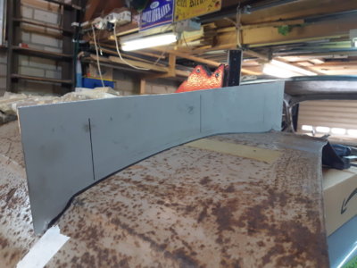
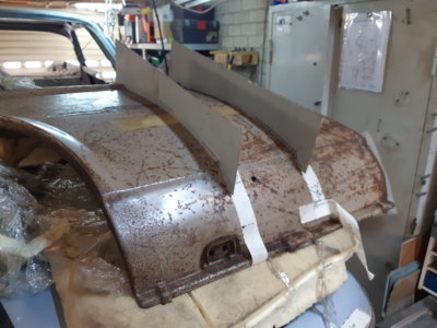
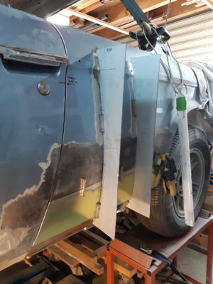
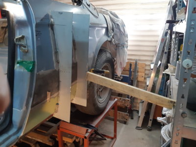
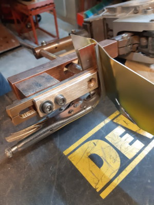
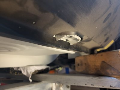
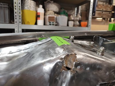
As I have finished the rear quarter panels, I am now focussing on the front end of my car. I have rust holes through the top sheet around the right strut. The Left side will likely have rust underneath as well.

20231106_105816.jpg 20231106_105749.jpg
What i can can also clearly see is that my complete front end has been chopped of at one point in its life:
- the front chin panel is post mid-1973 as it has the shorter air vent slots to accommodate for the larger US bumpers.
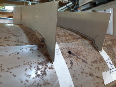
- there are numerous MIG welds on the front fenders to the connecting parts
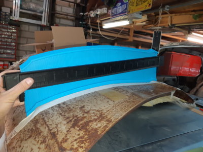
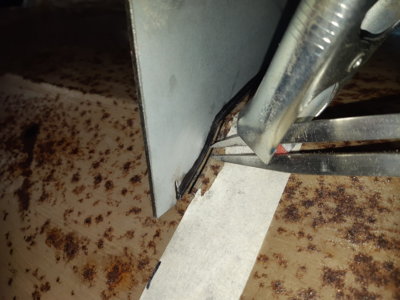
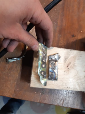
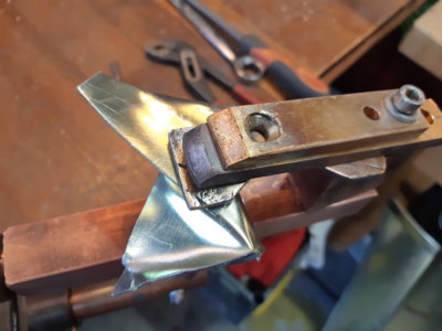
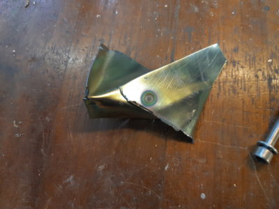
- the 4 individual connecting parts, 2 left, 2 right, are missing between the outside fender and the inner fender (in the picture those 2 W&N replacement parts are on the fender).

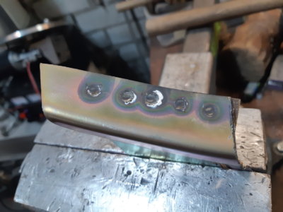
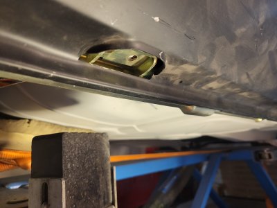
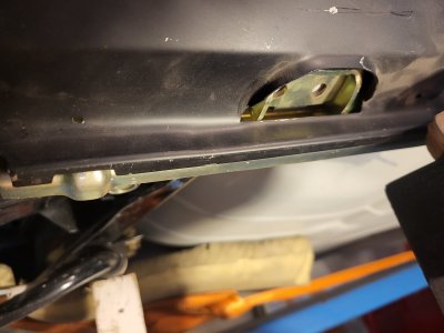
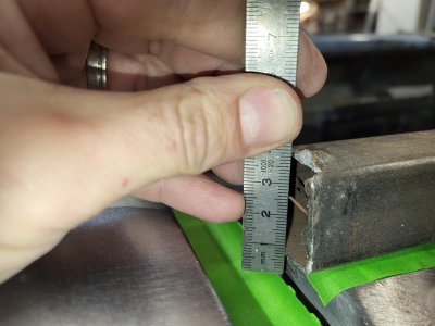
Now my question is the following: I think that the resulting position of the front of the car is about 7 mm (1/3rd of an inch) lower vs what it should be. I see 2 things that give me that idea:
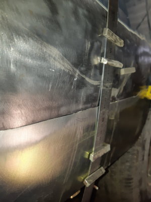
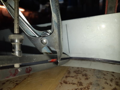
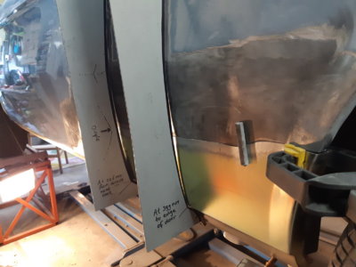
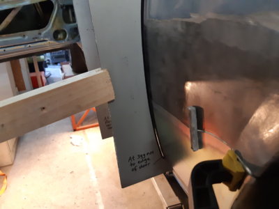
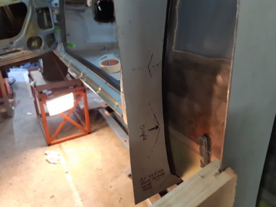
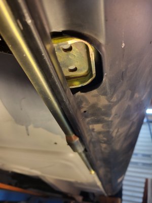
- the top edge of the strut support panel lies about 7 mm higher then the inner edge of the fender. (see image of the ruler, with the horizontal plate at the highest ridge of the strut panel)
- the 4 connecting parts that are missing, wouldn't even fit between the inner fender and the inside edge of the outer fender. They seem to be about
the same 7 mm higher then the available space.
20231106_110043.jpg

My question to the gruppe:
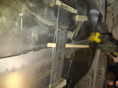
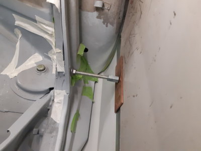
- Who can measure this distance on their car; providing their car hasn't been chopped up? It is measured by placing a flat plate on the highest edge of the strut tower, and extending that plane to the outside fender. what is then the distance to the edge of the raingutter of the fender? In my car it is 10 mm below as in the pic.
20231106_110015.jpg
fyi;
Here is the Stainless steel bodied E9. It seems to show that the highest edge of the strut lies is just above the raingutter edge of the fender (but the angle of the pic should be more horizontal to be sure):
1699274880720.png

some images from the web/Lezebre that are difficult to interpretate: From these pics I find it hard to estimate how high the lines are relative to each other.
If i take a guess; we'll see differences: the green car below shows clearly that the strut tower lies below the edge of the fender as it clearly exhibits an opening.
But I do not see this in other cars. (note: I have little info which cars have been rebuild during their lifetime)
1699272407103.png

This yellow car, like mine, i missing the 2 right hand connection parts between the inner and outer fender; but the strut lies clearly BELOW the outer fender.
1699272908476.png

and some other cars (CSL, from Lezebre)
1699272148569.png

this white one is documented to have new fenders:
1699273192877.png
1699273765766.png


1699272307931.png
1699272213145.png
1699273120033.png
1699273289834.png
1699273579466.png
1699273390526.png
 

Attachments

  • 20231106_143636.jpg
    20231106_143636.jpg
    382 KB · Views: 54
  • 20231106_143315.jpg
    20231106_143315.jpg
    342.1 KB · Views: 55
  • 20231106_143839.jpg
    20231106_143839.jpg
    249.9 KB · Views: 54
  • 20231106_143330.jpg
    20231106_143330.jpg
    286.4 KB · Views: 63
Last edited:

autokunst

Well-Known Member
Site Donor $$
Messages
3,608
Reaction score
2,622
Location
Milwaukee, WI
Hello Erik,
I always love these deep dives you do into a specific detail of our chassis, and I learn something new every time. Thank you for your attention to detail.

While my fender tops are in rough shape, and have been patched up in some spots, I believe them to be original to the car and in the original position. The area you are describing has not been fixed or modified on my car (that I can tell). And, since my chassis has the benefit of being bare metal, it is very easy to see the area and condition you are after. With that in mind, I offer the following images to add to your data. Unfortunately, I didn't see your straight bar photos until I had left the house. But I do have photos showing a smaller straight edge resting on the inner fender tops. As you will see in the images, I get a consistent measurement of 3mm on both sides. I hope this helps, and I look forward to seeing more information on this subject.

Left side:
20231106-left side 1.jpg
20231106-left side 2.jpg

20231106-left side 3.jpg


Right side:
20231106-right side.jpg
 

eriknetherlands

Moderator
Site Donor
Messages
2,760
Reaction score
2,000
Location
Netherlands, Eindhoven area
Great info! Exactly what I needed. You've got quite the job still at hand, those are some serious rust holes right there.
Yeah, I tend to deep dive before I take an angle grinder to the car. I can't measure anything when it's all apart like lego blocks.

I also note in your pictures, that the 2 short connection pieces between the inner and outer fender, are nicely following the raingutter of the outer fender, especially when it comes to the height: the bottom of those 2 connection pieces rest on the inner fender, and the vertical edge is just about as high as the top edge of the raingutter.

Would you mind measuring for me how far these 2 connections pieces are spaced apart? (it looks like rust ate quite a part of it, but the edges facing each other have remained partly in place)

Now with the myriad of different gaps I see on the pictures, i start to wonder if our coupes don't sag over time / when they get rotter.

Any other members having some measurements?
 
Last edited:

autokunst

Well-Known Member
Site Donor $$
Messages
3,608
Reaction score
2,622
Location
Milwaukee, WI
Would you mind measuring for me how far these 2 connections pieces are spaced apart? (it looks like rust ate quite a part of it, but the edges facing each other have remained partly in place)
I'll be honest, I haven't looked at the tops of the fenders in quite some time. The car is on a lift always and I generally only see this area from underneath - which looks considerably better from that vantage point. I don't want to say I'm discouraged, but I am a bit sorry I looked up there today. o_O

To answer your second question, I have measured both sides. The left side does seem intact and from what I can tell, correct. The gap between the pieces measures about 75mm. The right side was a little tighter at about 72 or 73mm.
20231106-separation.jpg
 
Top