Fixing that little rust spot...

eriknetherlands

Moderator
Site Donor
Messages
2,737
Reaction score
1,985
Location
Netherlands, Eindhoven area
continued from previous. (passenger floor welding)

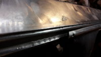
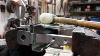
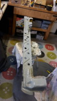
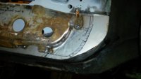
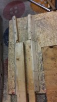
212533, checking and correcting flushness before and after tack welding
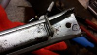
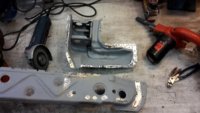
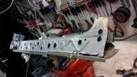
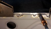
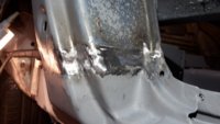
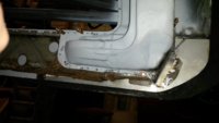
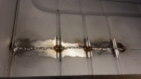
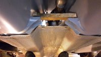
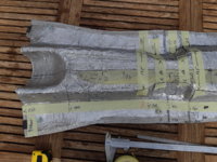
215536, butt welding the new panel to the rear floor (also new, installed earlier)
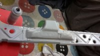
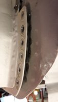
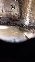
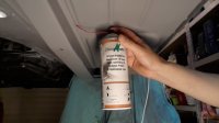
221131, my trick to get the epoxy as best as possible into the weld seam. I modified a spray head with a cleaned straw from an old oil spray can. [ edit 2018: I found out you can just buy these caps with straws over internet) Works better then just spraying and soaking; this gets more paint into the seam.
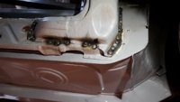
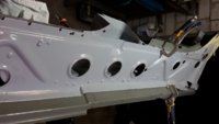
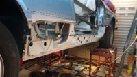
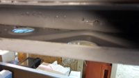
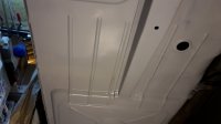
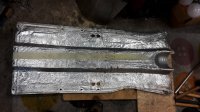
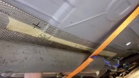
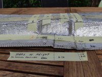
215635, front floor all welded up & finished.
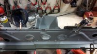
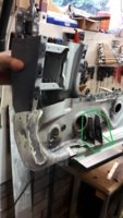
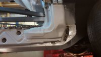
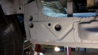
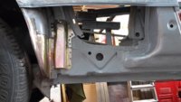
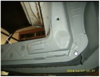
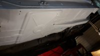
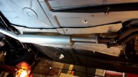
215749, full view of passenger side front and rear.
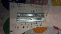
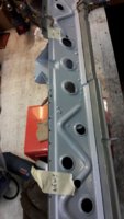
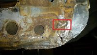
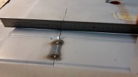
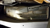
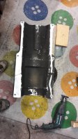
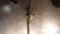
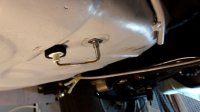
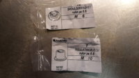
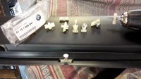
223136, welded 2 M8 nuts for additional heat shield (BMW PartNo: 51 48 1 832 850)
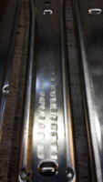
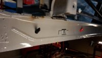
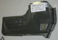
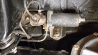
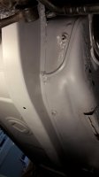
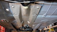
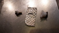
220250, heat shield installed.
 

Attachments

  • 20161002_212533.jpg
    20161002_212533.jpg
    716.7 KB · Views: 504
  • 20161002_215536.jpg
    20161002_215536.jpg
    371.6 KB · Views: 475
  • 20160905_221131.jpg
    20160905_221131.jpg
    515.5 KB · Views: 469
  • 20161012_215635.jpg
    20161012_215635.jpg
    344.4 KB · Views: 526
  • 20161012_215749.jpg
    20161012_215749.jpg
    355.3 KB · Views: 492
  • 20161103_220250.jpg
    20161103_220250.jpg
    216.7 KB · Views: 468
  • 20161103_223136.jpg
    20161103_223136.jpg
    168.1 KB · Views: 508
Last edited:

eriknetherlands

Moderator
Site Donor
Messages
2,737
Reaction score
1,985
Location
Netherlands, Eindhoven area
( edited July 2020 with plastic washer part number info for attachment to body. )
A side project of my sill and floor repairs; In the time that the car was driving, i was annoyed by the heat coming through the tunnel. Although the above heat shield will fix part of the problem, I decided to do a bit more. I wanted to do it now, as it required new attachment points to be made to the fresh new floors. So this was the time to do it.

I searched for half a year for what-looks-to-be-an-ideal solution; a heat shield of a E3 3.3 Li but it was nowhere to be found. Searched the Netherlands and Germany, visited 3 e9 wreckers but unfortunately no bingo. Purchased an e24 shield, and that didn't fit either.

( reference to thread http://www.e9coupe.com/forum/threads/heat-shield-project.20751/#post-182412)
So i opted to shape one myself: I had purchased a E60/E61 shield already, and deemed it previously to be way out for a bolt on fitting. But the positive side of the E60/E61 heat shield was that it had square meters aplenty. This allowed me to flatten most of it, keeping the large curve around the guibo, and reshape the rest. I choose to fit it between the prop shaft and the exhaust to keep the prop shaft as cool as possible (rubber parts, bearings etc). There's about 4 to 8 cm's of clearance (1,5-3 inch) in most places.
Part number of the E60/E61 heat shield is 51-48-7-033-0-723

To do this I build a wooden jig, making a negative copy of the body, allowing to use a rubber mallet to pound the curves and depressions in. Attached the process and end result.

pics:
- non fitting E24 heat shield
- E60/61 part with identification numbers
- wooden jig
- wooden jig front end
- forming process; flattened and made the long tunnel hugging form
- 2nd step, space for center bearing brackets
- Attachment method, plastic Polyamide washers for electric isolation to prevent aluminum to steel contact corrosion. Hopefully they are temperature resistant enough.
- made a small tool, a '3rd hand' to hold the M6 weld nut to body with a magnet, prior to welding it on the underside of the floor.
- Two pics showing the end result, mounted under the car
- part number of the plastic washers added as well. The bolt is an M6*16.
 

Attachments

  • E24 heat shield; no luck under E9.jpg
    E24 heat shield; no luck under E9.jpg
    294.3 KB · Views: 458
  • BMW Part identification E60-E61.jpg
    BMW Part identification E60-E61.jpg
    825.2 KB · Views: 473
  • wooden jig front end.jpg
    wooden jig front end.jpg
    725.7 KB · Views: 474
  • E60-61 heat shield reshaped 1st step.jpg
    E60-61 heat shield reshaped 1st step.jpg
    692.9 KB · Views: 462
  • E60-61 heat shield step 2 center bearing bracket cleareance.jpg
    E60-61 heat shield step 2 center bearing bracket cleareance.jpg
    555.1 KB · Views: 491
  • heat shield fitment method.jpg
    heat shield fitment method.jpg
    254.3 KB · Views: 470
  • third hand to aid in welding body nuts.jpg
    third hand to aid in welding body nuts.jpg
    344 KB · Views: 466
  • trimmed and held in place with magnets.jpg
    trimmed and held in place with magnets.jpg
    528.5 KB · Views: 472
  • overall view.jpg
    overall view.jpg
    515.7 KB · Views: 448
  • 3rd step of forming, making the 10 and 15 mm steps of rear footwell.jpg
    3rd step of forming, making the 10 and 15 mm steps of rear footwell.jpg
    410.5 KB · Views: 441
  • 20170307_213303.jpg
    20170307_213303.jpg
    250.4 KB · Views: 204
  • 20170307_213412.jpg
    20170307_213412.jpg
    211.9 KB · Views: 187
Last edited:

mulberryworks

Mr. Fixity
Site Donor
Messages
1,244
Reaction score
614
Location
Jacksonville FL
Excellent work. I've been pondering the same issue and have been thinking along the same lines. I picked up a shield from a Boxster that's large, but not quite as big as yours. Also made of textured aluminum.
I have some stainless steel that I was going to use at the front above the manifold. It will be much harder to work but I have some tools to help out.

This should also make the center bearing and giubo live longer.
Extra points for taking the time to give your photos descriptive file names, that helps a lot down the road when checking resources.

Ian
 

eriknetherlands

Moderator
Site Donor
Messages
2,737
Reaction score
1,985
Location
Netherlands, Eindhoven area
Advantage of the E60/E61 heat shield is that the large half dome depression for the guibo is in the right place, in more or less the right shape.
So I flattened the whole heat shield first, keeping just that half dome.

Oh, and it's large enough to overlap with the smaller heat shield (51481832850) covering the ends of the downpipes.

update july 2020: other images with dimension added


Erik.
 

Attachments

  • 20200707_170052.jpg
    20200707_170052.jpg
    473.4 KB · Views: 187
  • 20200707_170216.jpg
    20200707_170216.jpg
    337.6 KB · Views: 185
  • 20200707_170245.jpg
    20200707_170245.jpg
    295.2 KB · Views: 184
  • 20200707_170312.jpg
    20200707_170312.jpg
    337 KB · Views: 221
Last edited:

eriknetherlands

Moderator
Site Donor
Messages
2,737
Reaction score
1,985
Location
Netherlands, Eindhoven area
Yesterday, having drained the gas bottle of my welder, I dug into the trim installation of the outer decorative sill. As mentioned in other posts, the white clips used to mount the trim to the sill are tough to install. I also did not like the fact that these plastic clips are difficult to unfasten. I'd like to be able to remove any road dirt from internal area's to prevent it building up and create a rust trap.
So i've considered glueing the clips or making additional twist-n-lock bolts (like the 2 supplied with each trim strip), but looking at the white clips i came up with this solution:
I simply broke the round pin from the clip, ground off the 4 cilindrical hooks and tapped an M6 thread in the already existing 5.4 mm hole. The clips now snap into the outer trim, and allow a screw to be installed from the inside.

The clips are polyamide type plastic and with their thickness they are very well suitable to tap a thread in them.
They now install cleanly with a M6*10 bolt (use a plastic washer to prevent scratching the paint)

It is now a simple bolt-on, bolt-off attachement, allowing yearly spring cleaning to be done quickly. And I never have to unclip plastic clips, which usually snap in pieces....

Attached some pics.

Part numbers used:
Aluminium+rubber trims:
LH: 51131810560
RH: ...............559 They come equipped with 2 lock bolts at each end but require additional plastic clips.
Plastic clips: 51131808841; 12 needed.
 

Attachments

  • 1. Sill trims and decorative strips.jpg
    1. Sill trims and decorative strips.jpg
    502 KB · Views: 582
  • 2. Modification of sill trim clips 51 13 1 808 841.jpg
    2. Modification of sill trim clips 51 13 1 808 841.jpg
    401.4 KB · Views: 499
  • 3. Clip modification; pin removed, hooks ground off, M6 thread tapped.jpg
    3. Clip modification; pin removed, hooks ground off, M6 thread tapped.jpg
    361.9 KB · Views: 512
  • 4. Clip installed too deep.jpg
    4. Clip installed too deep.jpg
    234.6 KB · Views: 545
  • 5. effect of too deep installed clip; wrong angle.jpg
    5. effect of too deep installed clip; wrong angle.jpg
    418.1 KB · Views: 520
  • 6. Inside of outer sill showing M6 bolt heads but missing a nice plastic washer.jpg
    6. Inside of outer sill showing M6 bolt heads but missing a nice plastic washer.jpg
    556.4 KB · Views: 485
  • 7. RH trim on sill - final result.jpg
    7. RH trim on sill - final result.jpg
    334.3 KB · Views: 507
Last edited:

eriknetherlands

Moderator
Site Donor
Messages
2,737
Reaction score
1,985
Location
Netherlands, Eindhoven area
Jeez. It's been over 6 months since I posted something here on my own work.
So brief update;

I have taken the 4 seat rails apart. Last pic shows what's inside. I did not expect so many parts!
They were suffering from rust, looking uncool and having problems sliding smoothly. Although they did slide, there were hesitations; bumps when sliding.
So I dismantled them; the rough way. The 'overview' in the last pic was helpful getting everything back in place
.
Appearently one can also zinc coat them with taking them apart: much easier, but everything has pro's and con's:

Suprisingly, there are rubber O-rings inside. One was split and dislocated.
Also there were quite some depressions from the ball bearings and from the cilinders that are inside. These cilinders take quite some weight, and they also caused bumps to form. Both these marks have exactly the same pitch as the index system that is hand operated to slide the set for/back ward. I smoothed these bumps out as best as I could to get smoother sliding. (who doesn't want that :))

Some pics:
 

Attachments

  • e9 passenger rail.jpg
    e9 passenger rail.jpg
    137.2 KB · Views: 461
  • open rails.jpg
    open rails.jpg
    144 KB · Views: 437
  • opening up seat rails to remove bearings.jpg
    opening up seat rails to remove bearings.jpg
    216.7 KB · Views: 419
  • Ball rolling out.jpg
    Ball rolling out.jpg
    179.1 KB · Views: 413
  • Ball bearing caused depressions.jpg
    Ball bearing caused depressions.jpg
    135.8 KB · Views: 373
  • Source of non smooth sliding.jpg
    Source of non smooth sliding.jpg
    216.1 KB · Views: 393
  • seat rail components.jpg
    seat rail components.jpg
    196 KB · Views: 406
  • marked -p- for passenger and - x- for front and down facing.jpg
    marked -p- for passenger and - x- for front and down facing.jpg
    149.4 KB · Views: 393
  • remove balls & cilinders.jpg
    remove balls & cilinders.jpg
    155 KB · Views: 388
Last edited:

eriknetherlands

Moderator
Site Donor
Messages
2,737
Reaction score
1,985
Location
Netherlands, Eindhoven area
some more pics or the reassembly.

Bending the profiles open was a bet; I was note sure if I could 'close' the profiles again keeping them straight enough to run smooth. But they do if your careful not to deform parts that need to stay in shape.
I first tried hammering the sides without the aluminium spacer, but it only caused the midsection to buckle. So i needed to force it in place somehow. Notice how (see pic) the profile is clamped in the vice, using the aluminium spacer to force the midsection to stay flat. Using the hammer now, it deforms the metal back into it's orginal 90 degree radius. Don't forget reinstalling the balls and cilinders with rubber O-ring.

While bending the profiles back, carefully measure with a caliper if they are getting close. I was amazed by how easy it is to get the profile width within 0,1 mm correct again.
 

Attachments

  • rail parts cleaned, ready for zinc.jpg
    rail parts cleaned, ready for zinc.jpg
    241.1 KB · Views: 352
  • fresh zinced.jpg
    fresh zinced.jpg
    291.6 KB · Views: 354
  • seat rails- cilinders inside the rails.jpg
    seat rails- cilinders inside the rails.jpg
    132 KB · Views: 363
  • closing seat rails again after reassembly.jpg
    closing seat rails again after reassembly.jpg
    181.2 KB · Views: 370
  • new rubber O-ring for cilinders.jpg
    new rubber O-ring for cilinders.jpg
    345 KB · Views: 337
Last edited:

eriknetherlands

Moderator
Site Donor
Messages
2,737
Reaction score
1,985
Location
Netherlands, Eindhoven area
And here's my progress with the Right hand side Sill over the past months.

In 2016/2017 I choose to keep the inner sill in the car, connected to the A & B-pillar and also tied in with the internal reinforcements that I welded in. this was done to keep the car straight and square.
This allowed me to clean the inner sill from both sides as also the entire right side floor was out at some point in 2017. I also cut out and fixed the rust on the lower sections of the A and B Pillar already (see previous posts)

Over the last 6 months I welded the A and B pillar reinforcements back onto the Intermediate sill, while all were temporarily mounted with Cleco's inside of the car. This gave exact positioning of the parts, but it alos allows to treat the front & back of your welds thoroughly as I could take the intermediate off again and place it on the workbench and grind, clean and paint everything, including the insides of the A and B pillar lower ends.
Image 4/5/6 show this, and it also offers a unique view to understand how these parts are positioned relative to each other.

The lower B-pillar was modified to have a water drain hole at each end, versus just one in the middle. think it works better this way. Also reinforcements were welded in at the front Jack pick up point. (see green line in pic) Not that I'm going to use them, but who knows in the future somebody else will try them. This way they won't bend inward as easy as in the original weaker OEM construction.
 

Attachments

  • A-pillar prep.jpg
    A-pillar prep.jpg
    200.5 KB · Views: 373
  • A pillar  bottom welded back in.jpg
    A pillar bottom welded back in.jpg
    149.6 KB · Views: 382
  • a and b pillar welded on.jpg
    a and b pillar welded on.jpg
    213.3 KB · Views: 393
  • Intermediate and outer sill; but outside of the car.jpg
    Intermediate and outer sill; but outside of the car.jpg
    203.8 KB · Views: 371
  • Intermediate sill, B-Pillar and outer structural sill on the workbench.jpg
    Intermediate sill, B-Pillar and outer structural sill on the workbench.jpg
    138.7 KB · Views: 359
  • Intermediate, B-pillar, and outer sill, outside of the car.jpg
    Intermediate, B-pillar, and outer sill, outside of the car.jpg
    187.5 KB · Views: 360
  • Lower B-pillar on Inner sill.jpg
    Lower B-pillar on Inner sill.jpg
    165.1 KB · Views: 439
  • Front jack point reinforcements.jpg
    Front jack point reinforcements.jpg
    193.4 KB · Views: 381
Last edited:

eriknetherlands

Moderator
Site Donor
Messages
2,737
Reaction score
1,985
Location
Netherlands, Eindhoven area
With these A&B pillars in place, I drilled two extra holes in the intermediate sill to get better access to all internal spaces when later I need to insert paint or wax. The holes correspond to the 20mm holes already present in the inner sill, which can be accessed from the interior side and are normally closed off with whote plastic caps. Now I can use these to also get wax one layer further into the sill.

I offered the intermediate sill (with the lower A&B pillar already welded on) back up to the car, and weld it in, closing the slits made in the A & B pillars. I'm getting better at welding, I am now confident enough to show that even the backside of the welds show nice penetration, and the beads overlap nicely. The pic is made through the round opening just above the lower hinge in the A-pillar / door jamb.

The intermediate sill is connected to the inner sill only through direct welds along the top, front and end. At the bottom the two do not meet, which makes it possible to go in and clean & paint the inside of the sill after welding.

last pic shows the bit made to finalize the rear wheel arch. I had it zinc coated, so it can be spotwelded later on to the outer skin, and still have a rust preventative coating on the flange that is directed at the wheel. All I can do to make it last another 50 years...

Next up is the outer sill!
 

Attachments

  • New wax injection holes in intermediate sill.jpg
    New wax injection holes in intermediate sill.jpg
    184.1 KB · Views: 360
  • original holes in inner sill (black & red pen), copied for wax injection.jpg
    original holes in inner sill (black & red pen), copied for wax injection.jpg
    135.3 KB · Views: 345
  • prep for welding- 3 sides cleaned- Intermediate sill to Inner sill at front wheel.jpg
    prep for welding- 3 sides cleaned- Intermediate sill to Inner sill at front wheel.jpg
    124 KB · Views: 355
  • welding prep - cleaned and positioned intermediate sill to inner sill.jpg
    welding prep - cleaned and positioned intermediate sill to inner sill.jpg
    214 KB · Views: 363
  • Intermediate welded to Inner sill- bottom of A-pillar.jpg
    Intermediate welded to Inner sill- bottom of A-pillar.jpg
    162.8 KB · Views: 350
  • Intermediate sill welded in place.jpg
    Intermediate sill welded in place.jpg
    219.9 KB · Views: 360
  • B-pillar welded up and ground flush.jpg
    B-pillar welded up and ground flush.jpg
    172.9 KB · Views: 354
  • inside of weldline in lower A-pillar-looking through opening in door jamb.jpg
    inside of weldline in lower A-pillar-looking through opening in door jamb.jpg
    244.8 KB · Views: 361
  • between inner and intermediate sill, cleaned and epoxy painted after welding.jpg
    between inner and intermediate sill, cleaned and epoxy painted after welding.jpg
    112.4 KB · Views: 361
  • 20170719_021210.jpg
    20170719_021210.jpg
    153.7 KB · Views: 344
  • 20171122_123719 Wheel arch -made by hand, zinced and ready for welding.jpg
    20171122_123719 Wheel arch -made by hand, zinced and ready for welding.jpg
    180.3 KB · Views: 398
Last edited:

autokunst

Well-Known Member
Site Donor $$
Messages
3,606
Reaction score
2,620
Location
Milwaukee, WI
Erik,
I love your methodology - great to see. Thank you for sharing your process. The car will be better than new.
 

eriknetherlands

Moderator
Site Donor
Messages
2,737
Reaction score
1,985
Location
Netherlands, Eindhoven area
Thanks Autokunst. I get real satisfaction out of thinking 'how can it be better'. But it takes a damn lot-a-time.

e.g another modification to prevent rust, different from OEM style, was to eliminate the gap that exists in the front wheel area between the lower A-pillar and the intermediate sill. In the normal construction, the intermediate sill has a 'nose' that peeps out from under the lower A-pillar reinforcement. For some strange reason, the A-pillar that goes over that little 'nose' doesn't close it off, but it leaves an opening above and below the nose. It is directed towards the front wheel. It is in an ideal position to suck up dirt and water from the front wheel. this then enters straight into the inner sill construction.
See pics from my solution, and the original panels. (reference to the perfect work done by MIklos @ CSL garage in Budapest on the Inka CSL)

Now I know that the car left the factory with a splash shield mounted on the A-pillar, but these are hardly water tight, screwed on using horrible paint scratching slide nuts, and actually requiring holes into the A-pillar. Quite often they are missing and so were mine. So I opted to just delete the 'nose' on the intermediate sill and remake the rusted out section of lower A-pillar so it fits tight over the sill, leaving no gap.
Also I deleted the openings in the A-pillar that accepted the slide nuts that position the splash shield. These slide nuts always scrape the paint off, and by definition, they are very close to water as the head of the screw is INSIDE the wheel splash area. The screw rusts, the clip rusts, and after a while the water gets into the inside of the A-pillar...Not good. So I deleted that.

Now I just have to find a way to mount that splash shield again.
Erik
 

Attachments

  • A Pillar Walloth and Neesch.jpg
    A Pillar Walloth and Neesch.jpg
    91.1 KB · Views: 365
  • water leak solution A-pillar Intermediate sill.jpg
    water leak solution A-pillar Intermediate sill.jpg
    196.9 KB · Views: 367
  • water leak solution A-pillar Intermediate sill 2.jpg
    water leak solution A-pillar Intermediate sill 2.jpg
    156.7 KB · Views: 379
  • water leak- original part with 'nose' that peeps out from under A-pillar.jpg
    water leak- original part with 'nose' that peeps out from under A-pillar.jpg
    292.8 KB · Views: 360
  • Miklos CSL Garage example.jpg
    Miklos CSL Garage example.jpg
    29.3 KB · Views: 351
Last edited:

Belgiumbarry

Well-Known Member
Messages
1,618
Reaction score
1,117
Location
Belgium
respect for your work Erik !!! those splash shields , are those still available ??? i don't have them on my cars.
 

eriknetherlands

Moderator
Site Donor
Messages
2,737
Reaction score
1,985
Location
Netherlands, Eindhoven area
Gransin,
Indeed I am planning to fit them. Could you share how you have mounted them? I am interested in ideas how to fix them, as I am now in the position to weld on nuts/bolts/brackets to the A-pillar / inner wheelhouse.
 

Gransin

Well-Known Member
Site Donor
Messages
1,529
Reaction score
1,272
Location
Vasa, Finland
Gransin,
Indeed I am planning to fit them. Could you share how you have mounted them? I am interested in ideas how to fix them, as I am now in the position to weld on nuts/bolts/brackets to the A-pillar / inner wheelhouse.

Okay! The picture I attached is not my car, and I've not yet mounted them on mine but will do in a couple of weeks. My problem is that both my front wheelhousing structure (lower A-pillar) is different than stock, the right side is the most modified, so installing them will require some modifications to the lokari, and I don't think it will be a good reference to anybody elses installation.

Here is the thread from where I took the picture:
https://e9coupe.com/forum/threads/new-fender-liners-lokari.4463/

Dequincy also have an installation thread, but you need the photobucket addon for Chrome or Firefox to see them.
https://e9coupe.com/forum/threads/lokari-fender-protection-installation.13036/
 

eriknetherlands

Moderator
Site Donor
Messages
2,737
Reaction score
1,985
Location
Netherlands, Eindhoven area
Looked at the Lokaris today.
I'm not fond of new holes, although I know that they should be dry (when the bracket is located behind the locari's)
I would search for an option to mount them using the ends of the bolts that secure the front bumper. (are they on EU cars as well ?)
Secondly, I read that the rubber lips are attached with steel staples. That's not really what I expected.... why didn't they use stainless steel rivets instead?
IF I ever see a local E9 with lokari's I'll think i'll try toget a template from them and just make them myself how I think they should be.... and save 100 euro's having fun doing it.

Anyway; other topic.
I have taken out the rear axle some time ago, and "while-at-it", took the brake balancer out for a good clean.

Now the cast iron block, large nut and spring housing have been cleaned, zinc coated, epoxy sprayed and black finished, but it will be a while before they get installed.

I did not remove the glued & sealed in screw that sets the spring pre-compression; it was zinced with it in place. It came back looking just fine. Which is a gamble, as I will only know if it really works when I start driving.....
Note that the manual says "do not touch" the setting, as it balances the brake pressure from L to R wheel.

All I need to do this evening is reassemble the components.... and update this thread with a "Ready! " pic
Edit: Done. Use a 32 mm socket to tighten the large cap.
 

Attachments

  • brake distributor rear prior to refresh.jpg
    brake distributor rear prior to refresh.jpg
    260.6 KB · Views: 348
  • disassembly.jpg
    disassembly.jpg
    290.1 KB · Views: 348
  • brake distributor rear - seal - .jpg
    brake distributor rear - seal - .jpg
    206.6 KB · Views: 337
  • spring force adjustment DO NOT CHANGE.jpg
    spring force adjustment DO NOT CHANGE.jpg
    296.5 KB · Views: 348
  • brake distributor rear unscrew cap .jpg
    brake distributor rear unscrew cap .jpg
    240.3 KB · Views: 331
  • brake distributor rear - piston removal - .jpg
    brake distributor rear - piston removal - .jpg
    204.3 KB · Views: 335
  • brake force distributor rear.jpg
    brake force distributor rear.jpg
    137.8 KB · Views: 321
  • 20180116_224045.jpg
    20180116_224045.jpg
    123.4 KB · Views: 322
  • 20180116_224229 -ready.jpg
    20180116_224229 -ready.jpg
    173.1 KB · Views: 311
Last edited:

mulberryworks

Mr. Fixity
Site Donor
Messages
1,244
Reaction score
614
Location
Jacksonville FL
Looked at the Lokaris today.
I'm not fond of new holes, although I know that they should be dry (when the bracket is located behind the locari's)
I would search for an option to mount them using the ends of the bolts that secure the front bumper. (are they on EU cars as well ?)
Secondly, I read that the rubber lips are attached with steel staples. That's not really what I expected.... why didn't they use stainless steel rivets instead?
IF I ever see a local E9 with lokari's I'll think i'll try toget a template from them and just make them myself how I think they should be.... and save 100 euro's having fun doing it.

I'm in agreement with you on the Lokaris. I have a bead roller from Eastwood and am planning to make my own versions once I create cardboard templates. Rather than stainless steel, I'd probably use aluminum rivets. Easier to work with and there's less chance of galvanic corrosion since there won't be a difference in electrical potential between the two materials.

From https://en.wikipedia.org/wiki/Galvanic_corrosion

The unexpected fall of a heavy light fixture from the ceiling of the Big Dig vehicular tunnel in Boston revealed that corrosion had weakened its support. Improper use of aluminum in contact with stainless steel had caused rapid corrosion in the presence of salt water. The electrochemical potential difference between stainless steel and aluminum is in the range of 0.5 to 1.0V, depending on the exact alloys involved, and can cause considerable corrosion within months under unfavorable conditions. Thousands of failing lights would have to be replaced, at an estimated cost of $54 million.​
 

Belgiumbarry

Well-Known Member
Messages
1,618
Reaction score
1,117
Location
Belgium
Erik, perhaps a typo ??? but that balancer is for front/rear balance , nothing to do with L and R wheel.
The set screw is not that important .... if i remember right it holds the brake pressure as fronts up to 25 bars and from then it reduces the pressure so not to go equal higher as pedal/front pressure.

You can test it on a wet road , hard braking should not lock rear wheels first !
On rallycars we remove that ( and a simple T in it ) but have a balancer in the car so we can even change the setup for optimum dry/wet driving.
Thats why rallycars use the ( hydraulic ) handbrake, locking the rear wheels to get the car sideways.

ProportioningValve.jpg
 
Last edited:

eriknetherlands

Moderator
Site Donor
Messages
2,737
Reaction score
1,985
Location
Netherlands, Eindhoven area
One of the targets was to learn with this thread, so a thanks to Belgium Barry and Mulberryworks;
Lokari's: yup indeed correct; Alu should ideally be combined with Alu. Having studied Materials Engineering I think I should hand in that degree....
Brake balancer: ok, learning here. looking at the internals I really thought it balanced L vs R. So got that wrong...I'll keep the wet road test in mind should I ever get over finishing the bodywork...

Thanks for the education guys!
 
Top