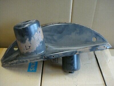
I'm not certain as I didn't climb up in there too thoroughly, but I think that is a forming wrinkle. You can see a couple more at 6 and 8 olcock on the left tower photo. But if it is a crack, I will address it! Thanks!(Ps , in the first pic , right rear, there is another crack going toward 6 o'clock staring at the opening. )
You are using an out of date browser. It may not display this or other websites correctly.
You should upgrade or use an alternative browser.
You should upgrade or use an alternative browser.
Heartbreak-broken rear shock mount
- Thread starter Stevehose
- Start date
When I was welding up the lengthy fatigue cracks in the frame head of the pan for my '54 Beetle, I could see how far the cracks extended by heating along one side of the crack with the oxy/acetylene torch. The heat wouldn't transfer easily to the other side showing the line of the flaw. Our shock mounts are small and thin enough that welding up the cracks will be fairly simple, though with an arc welder they won't be as easy to see.I'm not certain as I didn't climb up in there too thoroughly, but I think that is a forming wrinkle. You can see a couple more at 6 and 8 olcock on the left tower photo. But if it is a crack, I will address it! Thanks!
From a page on crack detection:
There are three methods of crack detection especially for carbon steel, these are;
Magnetic particle testing or inspection,
Liquid penetrate inspection,
Eddy current testing method
The liquid penetrant inspection usually involves the use of a dye and it is a very low-cost method of inspecting surface breaking defects, especially in non-porous materials. This method of crack detection can be used in detecting hairline cracks, porosity on the surface of material, leakages in new products and fatigue cracks present in in-service components. The liquid penetrant inspection makes use of low surface/tension fluid to penetrate dry surfaces, to detect flaws.
Once the fatigue cracks have been welded, there will no doubt be stresses created by the steel shrinking as it cools. This is one reason spot welding is used so widely in car bodies, each weld is very small and there isn't much heating of the surrounding area, reducing stress. There is a huge amount of science around the treatment of steel after welding so it's a little bit difficult to sort out what might be the best course of action for this repair.
Heating the steel during welding should reduce some of the work hardening that has resulted in the fatigue cracks, but since the cracks could be small, the Heat Affected Zone may not encompass the whole top of the mount, leaving some steel still fatigued and now stressed even more by the shrinking of the nearby weld.
It seems most auto body work ignores this issue, but here we have evidence of the fatigue cracking that happens when the work-hardened steel at the top of the mount ages under use.
Adding enough steel to the mount, either by welding or bonding should add enough strength to keep future failures at bay, side stepping the question of residual stresses but I will continue to look into this question of post weld treatment of steel to see what I might do for my own rear shock mount repair and post my conclusions.
Fortunately, our cars don't use the high strength steel, often heat treated, that modern car bodies use to reduce weight as that would add another variable to this repair.
Here's a link to one of the many pages I've found that talk about the various treatments of welded steel.

Heat Treatment of Welded Joints - Part 1
Before discussing the range of heat treatments that a metal may be subjected to, there is a need to clearly define what is meant by the various terms used to describe the range of heat treatments that may be applied to a welded joint.
 www.twi-global.com
Ian
Here is a NOS set of rear shock towers which seem to be the solution for someone doing a restoration


 …..
…..
BMW E9 3,0 CS CSi CSL 2800CS - Radhaus hinten links Dom | eBay
Entdecken Sie BMW E9 3,0 CS CSi CSL 2800CS - Radhaus hinten links Dom in der großen Auswahl bei eBay. Kostenlose Lieferung für viele Artikel!
www.ebay.de
Interesting. I have different picture of NOS part but probably it was bigger part drilled from or fitted but removed after.
Unfortunately the top is not well visible.
I might be wrong but it looks like the top reinforcement ring has been welded around (factory? Don't think so) as on other, same part (non NOS) on his other auction.
Unfortunately the top is not well visible.
I might be wrong but it looks like the top reinforcement ring has been welded around (factory? Don't think so) as on other, same part (non NOS) on his other auction.
Do you have a measurement for the thickness of the cylindrical wall of the mount?
FYI,
This is my spare strut top that I lent to @mark99. As you can see, the walls are quite thick. To
remove the whole thing properly, you need to drill the spot welds out of the wheel housing, then cut the seam welds on the inner rear fender. It’s in there!
Do you have a measurement for the thickness of the cylindrical wall of the mount?
I don’t. Parts are on loan.
Any update on that conversation, Chris?It's made by Tangerine Racing. http://www.tangerineracing.com/chassis.htm
I've gotten to know the owner, Chris Foley, having bought most of his stuff for my 914 build! I'd be happy to contact him and get the specifics. Maybe we could get his input on adapting his stuff to an E9?
Any update on this, @Krzysztof ?Gentleman,
While contacting Tlocznia Blach for other topic I asked about the possibilty of making such a part exactly matching rear shock.
The feedback is it is possible for half a price of the pipe cap. : ~$40
What do you think?
Any update on this, @Krzysztof ?
Krzysztof said:
Gentleman,
While contacting Tlocznia Blach for other topic I asked about the possibilty of making such a part exactly matching rear shock.
The feedback is it is possible for half a price of the pipe cap. : ~$40
What do you think?
I'm thinking we don't want an exactly matching part since the stock one has proved to be inadequate. I'd vote for something thicker and large enough to be welded onto the curved part or even the sides if possible. Something in the 50% to 100% thicker range perhaps. The strength of a component isn't quite linear to the thickness, 50% greater thickness should result in a bit more than 50% greater strength. A too thick part can make welding to the thinner metal more difficult.
My 2¢.
I should have been more specific. Later in the thread we discussed making a slightly smaller version of the top that can be pushed in from the bottom and held on by some industrial 3M adhesive. No welding involved. Just widening of the original opening first.I'm thinking we don't want an exactly matching part since the stock one has proved to be inadequate. I'd vote for something thicker and large enough to be welded onto the curved part or even the sides if possible. Something in the 50% to 100% thicker range perhaps. The strength of a component isn't quite linear to the thickness, 50% greater thickness should result in a bit more than 50% greater strength. A too thick part can make welding to the thinner metal more difficult.
My 2¢.
Either that or @tygaboy sandwich reinforcement idea
Any update on this, @Krzysztof ?
Tlocznia is able to produce the type which will be widely approved by potentially interested people. That was the statement and still is.
As far as I see the number of ways is bigger than one or two, so it is putting any "production" approach under question mark.
There are at least three solutions people would like to follow. Not sure there is any so called business case than.
I can ask for more details once there will be one, leading solution of there will be an interest.
Note:
Theoretically original part reproduction has much more chances worldwide as it is NLA and it is expected some would like to exchange the top part of the column from damaged to new piece.
---------------------
My few cents (not being in relation to what can be ordered).
My personal feeling for today, after reading all the topic and being a newbie is, thicker material will not make the topic solved as the forces will move to the edge line along with thickness change. I was learn too rigid design is not the best approach. Material should have some movement. Complete E9 body is very elastic by design I was told. That was an approach used by car manufacturers.
I'm not fully convinced about crown like design and glue. I would like to see it after few years of usage. For today this is completely new approach, never used.
It does not mean I'm against it - just careful.
I'd like to keep the originality of the suspension which means part should allow to use all genuine parts as for suspension and elephant skin.
As it was few times mentioned, we can't judge the rear column as badly designed. It's best before time just passed many years ago as for other metal and rubber parts E9 is made of.
E9s have a lot of other, more severe chassis-related problems after 50 years of usage.
Design as was is fine as long it will be protected with point or seam welds which was confirmed several time during E9 restorations and it is working fine for ones who's made it. It should survive above our era freely as long car is not used for racing or is not a restomod with Tesla engine etc. But this require many other modifications User is responsible to implement.
I took the photo Markos posted of the cut-off shock mount and use the image analysis feature of Photoshop along with other posted dimensions of the shock mount to calculate an approximate thickness of the sidewall of the shock mount. The photo has some camera movement reducing the areas of the wall that can be closely measured.I don’t. Parts are on loan.
I got a range of values between 2mm and 2.5mm and I think it is likely closer to 2.
Similar measurements on Autokunst's photos of his stripped shock mount for the OEM spot-welded washer on top of the mount yield a rough thickness range of 1.5mm to 1.75mm. This range is confirmed by measurements on the photo of the NOS shock mount part posted above.
By themselves, these approximations of metal thickness aren't very useful, but at least set some rough boundaries on what we're discussing.
Last edited:
check this out, non wimpy epoxy, Belzona epoxy
I took the photo Markos posted of the cut-off shock mount and use the image analysis feature of Photoshop along with other posted dimensions of the shock mount to calculate an approximate thickness of the sidewall of the shock mount. The photo has some camera movement reducing the areas of the wall that can be closely measured.
I got a range of values between 2mm and 2.5mm and I think it is likely closer to 2.
Similar measurements on Autokunst's photos of his stripped shock mount for the OEM spot-welded washer on top of the mount yield a rough thickness range of 1.5mm to 1.75mm. This range is confirmed by measurements on the photo of the NOS shock mount part posted above.
By themselves, these approximations of metal thickness aren't very useful, but at least set some rough boundaries on what we're discussing.
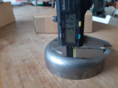
Perhaps much easier to measure at the flange where it is welded inside the wheel well to the body: I get 2.1 /2.2 mm, as it has a base paint.
And the ring is also 2mm, measured with a caliper on the top, making practical use of huge speaker holes for access.....
Yes, as much as I don't like the speaker holes that seem almost universal, they do provide good access to the top of the shock mount. I'm on the fence as to whether I'll remove my speakers and weld up the holes. I think I'd really rather listen to the music of the engine when driving this car. I may just put some small speakers in the dash.Perhaps much easier to measure at the flange where it is welded inside the wheel well to the body: I get 2.1 /2.2 mm, as it has a base paint.
And the ring is also 2mm, measured with a caliper on the top, making practical use of huge speaker holes for access.....
Thanks for the measurements. That's a great help. I'm looking at getting some reinforcement parts cut out by sendcutsend.com as their minimum order of $29 includes free shipping. I'm still making some design adjustments but it looks like parts prices could be as low as $10 each for 3mm stock. These cut out parts would still need to be formed to fit into or onto the mount cylinder, but I'm working on that.

Last edited:
Peter, please do let us know about your project. Just seeing those pictures make me cry. If there is a way to prevent it with a brace I think that is a great idea.I may not have this in time but I'm working with my neighbors who build custom instrumentation for oil pipelines and they have a pretty extensive machine shop across the parking lot from us here at work. I want to develop a brace that solves this problem without any welding, however will require 2 holes to be drilled in the trunk floor at the base of the shock tower and be tightened around the smaller cone that the rear shock attaches to. It will also include a ring around the top where Steve's tore. This will transfer the stress to the floor, which can be braced from below. I will check on the progress later today after a meeting I have. I started working on this when I noticed that the Polaris coupe had no additional welding on top and I think the Bilstein shocks do cause additional stress there because they are harder to compress and the springs take less of the burden.
As a reminder to the group, a replacement part was made for this purpose before by a member of the German E9 club .
See here, post #62 with the info kindly shared by @Ulrich 3.0 CSA .
 e9coupe.com
I have a set that i purchased ~8 years ago as insurance from Ulrich. Those parts were used satisfactory by other members.
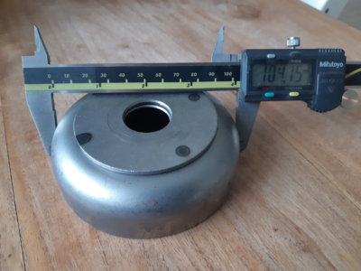
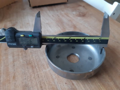
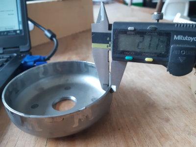
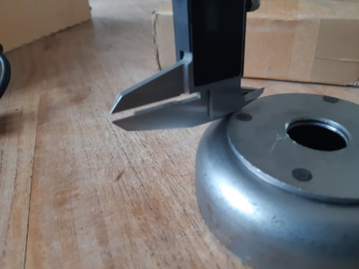
As it may be useful.for others, here are the dimensions:
The dome itself is made from 2 mm material, the disc on top is made from 3 mm material.
OD of the dome is 104 mm,
ID is 100 mm.
The radius (not easy to measure with a caliper) is about 13 +_0,5 mm on the outside.
See here, post #62 with the info kindly shared by @Ulrich 3.0 CSA .
Heartbreak-broken rear shock mount
Yes, I haven't measured yet but the thickness could very well end up that much. I don't know anything about welding so if it is better to weld the disk inside the tower instead of on top like a cap for strength then so be it. It would make the disk all the much thicker but the dish out/bevel...
I have a set that i purchased ~8 years ago as insurance from Ulrich. Those parts were used satisfactory by other members.
As it may be useful.for others, here are the dimensions:
The dome itself is made from 2 mm material, the disc on top is made from 3 mm material.
OD of the dome is 104 mm,
ID is 100 mm.
The radius (not easy to measure with a caliper) is about 13 +_0,5 mm on the outside.
Attachments
Last edited:
This is an excellent reproduction of the stock shock mount top. It looks to be a bit thicker so that's good. Once the top of the existing mount is removed, this could be welded on and a near perfect stock appearance would be the result.As a reminder to the group, a replacement part was made for this purpose before by a member of the German E9 club .
See here, post #62 with the info kindly shared by @Ulrich 3.0 CSA .
Heartbreak-broken rear shock mount
Yes, I haven't measured yet but the thickness could very well end up that much. I don't know anything about welding so if it is better to weld the disk inside the tower instead of on top like a cap for strength then so be it. It would make the disk all the much thicker but the dish out/bevel...
I have a set that i purchased ~8 years ago as insurance from Ulrich. Those parts were used satisfactory by other members.
As it may be useful.for others, here are the dimensions:
The dome itself is made from 2 mm material, the disc on top is made from 3 mm material.
OD of the dome is 104 mm,
ID is 100 mm.
The radius (not easy to measure with a caliper) is about 13 +_0,5 mm on the outside.
Unfortunately with only 4 spot welds holding the thicker washer to the top of the mount, upward forces from bumps will be focused on the areas around the spot welds which will eventually lead to the same sort of failure we have been seeing. Now we (mostly) don't drive our cars as many miles as when they were new and this is new and a bit thicker steel, so it seems unlikely that the fatigue failure we are seeing will reoccur during the remaining life of the vehicle. Track use of an E9 is a different story, of course.
Does Ulrich still make these?
My idea is that it's best to distribute the forces away from the top of the shock mount to reduce the stress on the steel, limiting its flexing and resulting fatigue. There are many existing stresses any car resulting from its manufacture. Stamping the panels induces stresses, the differential cooling around the welded areas causes stresses. The loading of the forces on the parts as it sits and drives causes varying stresses over time. These all work together inducing fatigue, weakening the metal. Eventually cracks will form and begin lengthen over time. When the cracks are large enough, sudden failure will occur.
Welding the edge of the washer to the shock mount cylinder is helpful in that it distributes the load away from the center, but at the cost of adding fixed stress to the steel as the weld cools and shrinks pulling on the steel in the Heat Affected Zone around it. Properly done, the weld area should be treated by Annealing, Normalizing or Tempering to relieve the stresses, but that's rarely done with auto body repairs, often simply relying on the part being oversized so there is sufficient strength to avoid future failures. We have seen that the top of a 50 year old shock mount isn't really quite strong enough to make this bet.
My proposed upgrade is using a multi-legged part that could fit inside the shock mount and be fastened with automotive body grade adhesive. This adds steel to the existing structure and takes the load of forces away from the center and distributes them to the sides of the shock mount cylinder that are firmly welded into the body at numerous points.
Laser cutting a shape that has no sharp corners should mean the part will have low internal stresses. The part has a large area and will be bonded to the mount over its entire surface so the loads from the shock will be well distributed. The 3M epoxy does not require elevated temperatures so there would be no additional stresses induced to the shock mount, unlike if it were welded in place. The repair will be virtually invisible except from below when changing shocks.
This would not be an appropriate repair for those that have already suffered catastrophic failure as it's a supplement to the existing mount, they would be looking for a part like Ulrich has produced.
It would be great to be able to run some finite element analysis on our issue here to see just what and where the stresses are, but that's a bit much effort for this issue so we'll have to muddle through.
Ha! Yes, Erik, that would have been a great solution. Unfortunately I have been in touch with Ulrich about it several weeks back and he does not have any more of them. I did not get the impression that he was planning on having them made again.As a reminder to the group, a replacement part was made for this purpose before by a member of the German E9 club .
See here, post #62 with the info kindly shared by @Ulrich 3.0 CSA .
Heartbreak-broken rear shock mount
Yes, I haven't measured yet but the thickness could very well end up that much. I don't know anything about welding so if it is better to weld the disk inside the tower instead of on top like a cap for strength then so be it. It would make the disk all the much thicker but the dish out/bevel...
I have a set that i purchased ~8 years ago as insurance from Ulrich. Those parts were used satisfactory by other members.
As it may be useful.for others, here are the dimensions:
The dome itself is made from 2 mm material, the disc on top is made from 3 mm material.
OD of the dome is 104 mm,
ID is 100 mm.
The radius (not easy to measure with a caliper) is about 13 +_0,5 mm on the outside.