Heartbreak-broken rear shock mount

mark99

Well-Known Member
Site Donor
Messages
1,505
Reaction score
260
Location
Kirkland WA
Yes, material fatigue is the cause of these failures. Spot welding the washer to the top might have been expedient, but fully welding a larger washer would have made all the difference. If they had put sufficient support under the stamped mount as well it would be much more robust as that would move the load from the top to the sides.
Note the size of the support metal on the underside of the front fenders as show in this photo of Markos' NOS fender attached below and also in this post: https://e9coupe.com/forum/threads/pending-30yo-nos-inner-fenders.39718/

Yes, the engine is up front and there are more cornering forces than the rear has to handle, but this under plate for the front shock is an order of magnitude larger than the washer in the rear, has stiffening ridges, a shape that curves 90° to spread the load to the side walls and edge welds in addition to many more spot welds.

Simply welding around the edge of the OEM washer at the top of the stock rear mount will greatly enhance the distribution of forces away from the small spot welds and the center where the shock is mounted, but if there are already cracks forming under the washer, that may not be enough. If we drill out the spot welds and examine the underlying metal, we could weld up any existing cracks before adding additional metal to strengthen this mount.
It might be possible to use eddy current testing or X-rays to look for cracks, but the cost of that would likely far outweigh the cost of realizing that the design is insufficient for half a century of spirited driving and simply doing the repair/upgrade.

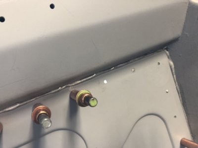
To quote my mechanical engineer friend who's now had a look at Autokunst's photos of his clean rear shot mounts:

Looks like the radial cracks are OEM as well:
View attachment 134454
The metal at the top of the stamping would have already been thinned from punching it into that deep well, then the center hole was peeled back to form a hem. And the meager spot welds holding the "washer" on don't pack it for the term.
I also suspect that if the washer was installed on the backside of this feature instead of on top, it would have made for a stronger assembly. But that would have complicated the welding operation, and affected the ride height, of course.


My thought is that the load should be moved at least out onto the curved part of the mount, and preferably down onto the sides so the loads will be along the surface of the sheet metal rather than at 90° to it. Running a few additional beads around the outside of the OEM washer would be one way of expanding the diameter of the steel supporting structure. Think of it as additive manufacturing in situ. But we are still left with using 50 year old metal with unknown stresses and fatigue patterns that could still fail.

My engineer friend and I have talked about a star shaped part that would distribute the forces over a larger area of the shock mount and would allow for much greater area of weld bead. And unlike getting a flat disk pressing into a cup shape, this would be easier to shape, once the pattern is cut by laser, plasma or water jet. It wouldn't look stock but my elephant skins are intact so the towers shouldn't be visible. I've got a basic plasma cutter so once I get some stock that's the right thickness, I think I'll cut some of these out and see how they might work for this. Welding the back side won't be fun, but should be doable.
One alternative would be to make the piece small enough to fit inside the tube and weld it from below. Not fun, but with longer legs, it can be welded primarily at the bottom rather than up at the top. I don't think the change in height would be too problematic.

View attachment 134443View attachment 134445View attachment 134444
a couple comments, on the front, it also takes the load from the spring
there is mention of ride height, I don't think that would be affected, this is only a shock
The star thing you are showing, that is what I was suggesting, only glued in from the bottom
 

Krzysztof

Well-Known Member
Site Donor
Messages
1,618
Reaction score
779
Location
Poland
I'm afraid any welding from the bottom side with elephant skin on can cause different damages of it including fire. I would be careful and took the risk of elephant skin damage by removing it.

Once removed we can have a better look on the top side.

I'm wondering how thick this "pot" from the underside can be without making any problems with suspension assembly later.

From force but also rust protection reasons it would be probably better to use complete pot shape rather than crown as to avoid humidity to go between original and new part. It would be very difficult to weld the crown all the way to protect it against rusting.
 

tferrer

Well-Known Member
Site Donor
Messages
2,153
Reaction score
2,336
Location
San Francisco, CA
Would definitely make it stronger but that looks like a fair amount of welding and the backside of the tower may be an awkward space to get the welder into.
 

mulberryworks

Mr. Fixity
Site Donor
Messages
1,244
Reaction score
614
Location
Jacksonville FL
Yes, welding the backside will be tricky. Mirrors and good hand/eye coordination would be needed. The welds don't have to be continuous, however.

Of course, any sort of work on the shock mounts would require removal of the irreplaceable elephant skins.

Shock clearance would have to be verified with any added material put inside the shock mount from below. The metal won't be very thick so that shouldn't be an issue., but check we must.

I'm warming up to mark99's suggestion of using automotive adhesives. This seems to be a case where the overlap of parts can be made large enough to give a substantial bond and sufficient strength to the final repair. With the parts well bonded together, no water should be able to get between them and thus eliminate potential future corrosion issues. This also preserves the stock look of the shock tower and the ability to install braces or battery mounts.

There are many variables to consider. The best adhesive to use, its required application and curing conditions, the allowable gap between the two parts to be bonded, what prep do the surfaces need, the adhesive's suitability for taking primers & paint and specifically which ones are recommended, length of time after curing that the adhesive can be left unpainted, cost and availability of the adhesive, storage life before use, once the application is started what is the working time, can the product be stored after partial use (ie to let another person repair their mounts, sharing the cost).
These are ones I've just gotten off the top of my head, I'm sure there are more. 3M has many such products and a quick google search found many more. I'll see if I can get a rep to offer an opinion on such use.
 

autokunst

Well-Known Member
Site Donor $$
Messages
3,607
Reaction score
2,620
Location
Milwaukee, WI
Simply welding around the edge of the OEM washer at the top of the stock rear mount will greatly enhance the distribution of forces away from the small spot welds and the center where the shock is mounted, but if there are already cracks forming under the washer, that may not be enough. If we drill out the spot welds and examine the underlying metal, we could weld up any existing cracks before adding additional metal to strengthen this mount.
I was about to post this very idea. It should be relatively easy to drill out the spot welds and reveal the top of the pressed sheet metal. From there, repairs can be made relatively easily (welding up existing stress cracks). I really like the idea of then welding the original washer around the perimeter (as well as re-welding the spot welds.

That said, the star idea would be considerably stronger, I think. I am leaning towards using the rear shock tower brace, so the original diameter may be important to me. Honestly, I am trying to approach this from an "improve, but do as little as necessary to gain far more strength over the original design". Seems this won't take that much given the pale solution that came from the factory.

Here's some more data to pour over. Following are photos of the insides of my "beautiful from the top" shock towers. You'll see that there is a stress crack spidering out from a spot weld on each tower. I'd say I am very thankful for this thread and discussion.
20220121-rt rear inner tower notes.jpg

20220121-lt rear inner tower notes.jpg
 
Last edited:

Krzysztof

Well-Known Member
Site Donor
Messages
1,618
Reaction score
779
Location
Poland
Just right in time!

Was the body dipped in some chemistry to get a rid of rust or was it water jet cleaning? Sorry. I should probably read about your project more before.

Nice pictures with description!
 

autokunst

Well-Known Member
Site Donor $$
Messages
3,607
Reaction score
2,620
Location
Milwaukee, WI
It was dipped to chemically remove all (most) paint, filler, undercoat, and rust. They called it an 80% cleaning. It came out clean enough to lick (paraphrasing from @Luis A. )

Once I am finished with metalwork, they dip it again and remove 100% of corrosion, then it will be e-coated (electrodeposition coating).
 

mulberryworks

Mr. Fixity
Site Donor
Messages
1,244
Reaction score
614
Location
Jacksonville FL
I've found a 3M product that seems to fill the bill for a bonding solution.
3M™ Impact Resistant Structural Adhesive PN 07333

I'll need to get more specific data and probably speak to a human to make the final determination. It's not cheap at $63 for 200ml (6.75 fl oz), but I think would be enough for both shock mounts. The TDS implies that some welding of the parts is preferred to bonding only, which makes sense.

Making the part to insert to close specs is the next big question. I'm sure they could be made manually with enough time to get them to fit well enough and that spec is yet to be determined, but that would preclude any sort of quantity production.


tygaboy

Well-Known Member
Messages
223
Reaction score
493
Location
Petaluma, CA
FWIW, I stamped my own fire wall panels and used the 3M 07333 to bond them to my V8 914. These aren't overlays - they're the "replacement" panels. As you can see, final plans call for rivets to be added around the borders but I've driven the car about 600 miles with only the adhesive. Mind you, this thing dyno'd at 518 hp/464 lb/ft so the bonded surfaces have seen some force. This stuff is STRONG. And in this E9 application, I'd be 100% confident using it - part fitment within spec, of course, as pointed out above.
 

Attachments

  • IMG_1629.JPG
    IMG_1629.JPG
    144.4 KB · Views: 105
  • IMG_2451.JPG
    IMG_2451.JPG
    370.3 KB · Views: 109
  • post-19241-1581555093_thumb.jpg
    post-19241-1581555093_thumb.jpg
    118.6 KB · Views: 92

bavbob

Well-Known Member
Site Donor
Messages
3,369
Reaction score
1,580
Location
Boston, Ma
So I decided to put my engineering hat on ( been 35 years) and think about this. Open to any and all criticisms to my statements:

1) When at rest, the rear of the car is supported almost totally by the springs, thus the spring rate and spring height set the stance. The force on the shock tower/subframe is negligible as it is only the compression of the shock itself, nothing more.

2) There will be a vertical, medial-lateral and front-back force generated with each bump. The component back/posterior is negligible since we assume the car is moving forward. The shock can only move parallel to itself so the tower has to handle everything tossed at it to allow only this parallel motion of the shock. The moment/torque is all handled by the tower.

3) Because the shock and spring are in parallel and not series, there will be an instantaneous hit on the tower before the spring/springrate kicks in. This hit will be determined by the shock stiffness/ability to deform and THE SHOCK TOWER RUBBER BUSHING.

4) Every hit to the tower is followed by a hit in the other direction to return to baseline/steady state SO FATIGUE is a big factor here.


I think this parallel setup is a design flaw because of 3) above. Feel free to not agree but then I ask why this also happens with the 2002 and if anyone has seen this happen to an E3 or E24. I do realize than current BMW's have gone back to shock and spring in parallel.

Therefore, your spring stiffness, shock stiffness, spring lag time (instantaneous ability to deform ie being in parallel to the shock), the lack of the ability of the shock to move in any direction other than parallel to itself, are all reasons why the towers crack.

I think to minimize this happening, reinforcement with something that can handle the fatigue factor is needed. Also I am now contemplating using a thrust bearing under the shock hat to allow some rotational motion of the shock shaft. I also think that routine changing of the shock tower rubber bushing should be done and never use poly for this application.

Now I hold my breath for the onslaught on this one time ChemE from those MechE's and Physics majors..............................Bfeng is perched I know it.
 
Last edited:

mark99

Well-Known Member
Site Donor
Messages
1,505
Reaction score
260
Location
Kirkland WA
not sure about this part (agree with every thing else, and I am not an engineer) "there will be an instantaneous hit on the tower before the spring/springrate kicks in"
The spring is already compressed, to support the car, for the wheel system to move in relation to the body the spring would have to compress more
 

tygaboy

Well-Known Member
Messages
223
Reaction score
493
Location
Petaluma, CA
So I decided to put my engineering hat on ( been 35 years) and think about this. Open to any and all criticisms to my statements:

1) When at rest, the rear of the car is supported almost totally by the springs, thus the spring rate and spring height set the stance. The force on the shock tower/subframe is negligible as it is only the compression of the shock itself, nothing more.

2) There will be a vertical, medial-lateral and front-back force generated with eat bump. The component back/posterior is negligible since we assume the car is moving forward. The shock can only move parallel to itself so the tower has to handle everything tossed at it to allow only this parallel motion of the shock. The moment/torque is all handled by the tower.

3) Because the shock and spring are in parallel and not series, there will be an instantaneous hit on the tower before the spring/springrate kicks in. This hit will be determined by the shock stiffness/ability to deform and THE SHOCK TOWER RUBBER BUSHING.

4) Every hit to the tower is followed by a hit in the other direction to return to baseline/steady state SO FATIGUE is a big factor here.


I think this parallel setup is a design flaw because of 3) above. Feel free to not agree but then I ask why this also happens with the 2002 and if anyone has seen this happen to an E3 or E24. I do realize than current BMW's have gone back to shock and spring in parallel.

Therefore, your spring stiffness, shock stiffness, spring lag time (instantaneous ability to deform ie being in parallel to the shock), the lack of the ability of the shock to move in any direction other than parallel to itself, are all reasons why the towers crack.

I think to minimize this happening, reinforcement with something that can handle the fatigue factor is needed. Also I am now contemplating using a thrust bearing under the shock hat to allow some rotational motion of the shock shaft. I also think that routine changing of the shock tower rubber bushing should be done and never use poly for this application.

Now I hold my breath for the onslaught on this one time ChemE from those MechE's and Physics majors..............................Bfeng is perched I know it.
I raised the rear shock towers in my 914 by 2" so the car sits lower by that amount but retains full suspension travel and keeps the suspension geometry in it's "sweet spot". The upper shock mount utilizes a captured spherical bearing to allow the shock to move freely (essentially swing) in response to the arc the lower shock mount scribes as it moves.
Would something like this help?

IMG_3478.JPG
IMG_3478b.jpg
 

mark99

Well-Known Member
Site Donor
Messages
1,505
Reaction score
260
Location
Kirkland WA
I raised the rear shock towers in my 914 by 2" so the car sits lower by that amount but retains full suspension travel and keeps the suspension geometry in it's "sweet spot". The upper shock mount utilizes a captured spherical bearing to allow the shock to move freely (essentially swing) in response to the arc the lower shock mount scribes as it moves.
Would something like this help?
that is an interesting piece of hardware, where did you get it?
 

tygaboy

Well-Known Member
Messages
223
Reaction score
493
Location
Petaluma, CA
that is an interesting piece of hardware, where did you get it?
It's made by Tangerine Racing. http://www.tangerineracing.com/chassis.htm
I've gotten to know the owner, Chris Foley, having bought most of his stuff for my 914 build! I'd be happy to contact him and get the specifics. Maybe we could get his input on adapting his stuff to an E9?
 

Norm!

Well-Known Member
Site Donor $
Messages
206
Reaction score
280
Location
Fremont, CA
not sure about this part (agree with every thing else, and I am not an engineer) "there will be an instantaneous hit on the tower before the spring/springrate kicks in"
The spring is already compressed, to support the car, for the wheel system to move in relation to the body the spring would have to compress more
I’m a Civil Engineer, and like bavbob, think I remember a small portion of my Physics, Dynamics and Fluid Mechanics from 50 years ago.
We know springs and shocks respond to forces differently. When a force caused by a bump or turn is applied to a spring it immediately compresses in response to the force. The faster you hit a bump the more a spring will compress since force equals mass times acceleration. As soon as the force stops, the spring starts rebounding as it tries to return to its original place based on the weight the car.
The shocks feel the bump force almost instantaneously when the springs start to compress and takes a portion of the bump force from the spring based on how stiff they are. Their job is to slow down and reduce the springs movement. The shock only resists speed of movement not magnitude or static weight (except a small amount with gas shocks). The faster the movement, the harder the shock resists the spring movement by forcing more gas or fluid through a very small orifice. As bavbob said, a car rebounding is also resisting that movement, so the force on the towers is constantly going back and forth work hardening the steel until it fractures. A harder shock has a smaller orifice so it resists movement more taking a bigger portion of the bump force which applies more force to the shock tower. A hard shock and fast driving over bumps over time leads to shock tower failure. A shock tower with a soft shock and smooth roads will probably never fail unless it is defective.
 

bavbob

Well-Known Member
Site Donor
Messages
3,369
Reaction score
1,580
Location
Boston, Ma
Agree. A bump is actually a pulse to the system and the shock is the dashpot that takes the hit instantaneously. The lag time from shock to spring kicking in is almost zero, but not quite.
 

eriknetherlands

Moderator
Site Donor
Messages
2,751
Reaction score
1,993
Location
Netherlands, Eindhoven area
Also an engineer's question; what else ( that fatigue) can it be?

Metals give way in 3 distinct manners:
-Rust (takes time)
-Overload (tensile, shear; all of this is rather instantaneous)
And fatigue.

It's surely not 1. You can safely rule our n0 2 as e9 being raced did not fail after lap 1. Or that massive pothole in 1978.

As it needs the time factor to die, I strongly believe it must be fatigue.

The spider cracks in the pics of Autokunst have the tell tale shape (irratic) of fatigue cracks also.
(Ps , in the first pic , right rear, there is another crack going toward 6 o'clock staring at the opening. )
 

Bmachine

Well-Known Member
Site Donor $
Site Donor $$
Messages
3,533
Reaction score
1,790
Location
Northern California coast
It's made by Tangerine Racing. http://www.tangerineracing.com/chassis.htm
I've gotten to know the owner, Chris Foley, having bought most of his stuff for my 914 build! I'd be happy to contact him and get the specifics. Maybe we could get his input on adapting his stuff to an E9?
That would be a great idea! Is the 914 prone to similar shock mount failure?
 

Bmachine

Well-Known Member
Site Donor $
Site Donor $$
Messages
3,533
Reaction score
1,790
Location
Northern California coast
I raised the rear shock towers in my 914 by 2" so the car sits lower by that amount but retains full suspension travel and keeps the suspension geometry in it's "sweet spot". The upper shock mount utilizes a captured spherical bearing to allow the shock to move freely (essentially swing) in response to the arc the lower shock mount scribes as it moves.
Would something like this help?

View attachment 134553View attachment 134554
Very interesting. Maybe this is another option for us. Instead of welding or gluing a new piece of some sort, have one ring inserted from the bottom and a mating one coming from the top with the two bolted together…. This would sandwich the weak section and distribute the load over a wide area.
 
Top