Heartbreak-broken rear shock mount

Krzysztof

Well-Known Member
Site Donor
Messages
1,658
Reaction score
792
Location
Poland
Gentleman, I read all the posts under the topic (I have no idea how I made it! ;-) ) and maybe it would be helpful to sum up all the options to help new readers as for other DYI threads but maybe from 2015 it is still to early to make it complete? What do you think?

What is missing here in my humble opinion is the voice of few experts more which I know there are on this forum. Does this problem interests only part of the Members or this topic is somehow difficult to be summarized by the recommended method?

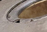
Looking on the damage Steve faced several years ago it looks for me (I'm no expert in car body topics) that the weakest points in shock mounts was:
a) few point welds holding upper place to the body "jar".
b) visible corrosion between the body steel and the upper place

It would make sense according to my experience.
Some of You were probably trying to separate two sheets of steel connected with spot welder.
There are two major scenarios/effect:
1. separation at the point weld - typically means insufficient quality of the welding
2. scratch like sheet metal damage on the line of many bending actions

Assuming car is running with stiff suspension on the bumpy road the forces are hitting that area and causing very specific damages: tearing the metal.

Following that, 2mm steel plus the plate are good enough, so the plates which were presented in the beginning as a repair have to work well.

I do agree change in the thickness (especially rapid) is worsening the situation.

Rounded pushed/stamped parts should be the best solution and cheapest for bigger orders.

If the damage is like on Steve's the pipe cap looks as the best solution once it will be very similar to original diameter but I would still recommend upper/lower reinforcement place welded where the shock absorber is mounted on top of the column.

Side topic:
Can anyone check if the diameter used on 2000CS or E10 are the same as for E9? That would be interesting as 2000cs was in fact built on E10 base. Unfortunately I have no access to any to be able to measure.
 

paul

Well-Known Member
Site Donor
Messages
321
Reaction score
305
Location
Australia, Queensland, Gold Coast
I cannot vouch for the accuracy of the OD of shock tower as I don't have a set of calipers ( I did say approx as I used a g clamp) All towers should be the same dimension in my opinion.
Regarding the welds inside the tower.......if people read my previous posts I did point out the difficulty in welding up inside the tower. Also plug welds are not as strong as a continuous weld. I only put forward the sketch of the inside mounted cap to help out those who did not like the outside mounted option (like I did on my car) 90 mm (3 1/2") fittings are not a common size but are still quite available. I have offered my advise to this blog and that's it.:cool:
 

Krzysztof

Well-Known Member
Site Donor
Messages
1,658
Reaction score
792
Location
Poland
Gentleman,

While contacting Tlocznia Blach for other topic I asked about the possibilty of making such a part exactly matching rear shock.

The feedback is it is possible for half a price of the pipe cap. : ~$40

What do you think?
 

adawil2002

Well-Known Member
Site Donor $$
Messages
5,187
Reaction score
3,050
Location
Brunswick, Maine
Gentleman,

While contacting Tlocznia Blach for other topic I asked about the possibilty of making such a part exactly matching rear shock.

The feedback is it is possible for half a price of the pipe cap. : ~$40

What do you think?

$40 for the material is inexpensive insurance for reinforcing the shock towers.
 

Bmachine

Well-Known Member
Site Donor $
Site Donor $$
Messages
3,534
Reaction score
1,792
Location
Northern California coast
Gentleman,

While contacting Tlocznia Blach for other topic I asked about the possibilty of making such a part exactly matching rear shock.

The feedback is it is possible for half a price of the pipe cap. : ~$40

What do you think?
I imagine that when you say "exactly matching rear shock", that means "Looking like the original... but much stronger", correct?

I really don't think the price is the important thing here, but rather the quality and the structural improvement. This is a pretty difficult repair to make and once you make it, you want to know for sure that the fix will last for 20 or 30 years. So if they can make a quality replacement top (not just a washer), I, and I am sure many others, would be very interested.
 

mark99

Well-Known Member
Site Donor
Messages
1,505
Reaction score
260
Location
Kirkland WA
"..exactly matching rear shock" what does that mean exactly? fits inside from the bottom? what does it attach to? How is it made?
my thought was to make something that fit in from the bottom and was attached to the sides of the tube with adhesive
That way, no cutting or welding
The only problems, making such a part, cleaning inside the tower 100% so the adhesive would stick
Industrial epoxy over a 'large' area like that would probably be a lot stronger than a weld
I have not figured out the best way to make it, NC or lathe would coat a lot, I don't think it would be in the $50 range, a 1 foot $' bar of steel is around $200, (which would make several) plus machining
 

Krzysztof

Well-Known Member
Site Donor
Messages
1,658
Reaction score
792
Location
Poland
It would be pressed part made out of steel ... But I'm aware there are different opinion how such a part might looked like (in, out, height etc.).
 

Krzysztof

Well-Known Member
Site Donor
Messages
1,658
Reaction score
792
Location
Poland
"..exactly matching rear shock" what does that mean exactly? fits inside from the bottom? what does it attach to? How is it made?
my thought was to make something that fit in from the bottom and was attached to the sides of the tube with adhesive
That way, no cutting or welding
The only problems, making such a part, cleaning inside the tower 100% so the adhesive would stick
Industrial epoxy over a 'large' area like that would probably be a lot stronger than a weld
I have not figured out the best way to make it, NC or lathe would coat a lot, I don't think it would be in the $50 range, a 1 foot $' bar of steel is around $200, (which would make several) plus machining

It can be in or out or edge to edge. Also the height is an open topic.

Is it possible to find a common requirement from You guys?
 

Krzysztof

Well-Known Member
Site Donor
Messages
1,658
Reaction score
792
Location
Poland
I think it is better than looking for $70 pipe cap, still requiring additional drilling etc, but might be I'm wrong here.
 

Bmachine

Well-Known Member
Site Donor $
Site Donor $$
Messages
3,534
Reaction score
1,792
Location
Northern California coast
It can be in or out or edge to edge. Also the height is an open topic.

Is it possible to find a common requirement from You guys?
I would think that if they can make a fresh top that fits inside, that would be the easiest solution for sure. Cutting and welding the top of these towers is difficult, painful and you have to contend with the issue of the gas tank being right next to it. So a reinforcement part that can slide up from inside and be secured with industrial adhesive (possibly with a couple of sport welds through holes drilled at the top of the existing towers) would be great.

You would still need to use a hole saw from the bottom in order to enlarge the original shock mount hole so that the rubber grommet would not need to fit through a double layer of steel there of course.
 

mark99

Well-Known Member
Site Donor
Messages
1,505
Reaction score
260
Location
Kirkland WA
you wouldn't need the weld, and the adhesive would go in first so a weld would only weaken the adhesive
 

Krzysztof

Well-Known Member
Site Donor
Messages
1,658
Reaction score
792
Location
Poland
Answer is simple: everything is possible as long as it will be an interest in a larger group as tooling, time and material costs.

Following the thread few ideas were used by different users on different preferences, knowledge and machine park availability.

Going will full restoration I would be for complete column or only a top. Once the car is stripped all cuttings and welding can be done without any risk.

I'm not an expert for car body design nor mechanical engineer to calculate the strength and welding/gluing recommendation so I will not be suggesting any way how it should be solved the better.
 

autokunst

Well-Known Member
Site Donor $$
Messages
3,610
Reaction score
2,623
Location
Milwaukee, WI
Hey all. I've been following this thread keenly. My assumption is that I'd want to replace my rear shock towers with one of these brilliant solutions prophylactically since I am doing everything else on the chassis right now. But then I took a look at my towers and they "appear" to be in great condition. I know that these failures are spontaneous, so if there is a good solution I might still perform the surgery now. What do you think the odds are that the originals will perform flawlessly for another 40 years?
20220109-left rear shock tower.jpg

20220109-right rear shock tower.jpg


I wanted to contribute to the size measurement. Rather than trying to get a caliper on it, I measured the circumference. Earlier, @mark99 suggested these towers would be slightly conical (I think the term he used is draft) so it could pulled off the press form. I can confirm this. As you'll see in the image, I was able to get a clean measurement 30mm down from the top, and I took a second measurement at 45 mm down. My math calculations suggest the diameter is 103.77mm at 30mm down; and 104.72mm at 45mm down. If you make some additional math assumptions, the measurement at the 15mm down position might be about 102.8mm (assuming this is before the radius kicks in). Hope this helps the strategists.
20220109-right rear shock tower MU copy.jpg
 

Bmachine

Well-Known Member
Site Donor $
Site Donor $$
Messages
3,534
Reaction score
1,792
Location
Northern California coast
Very useful measurements. Thank you Stephen.

As far as your question about yours working for another 40 years, sadly, upon receiving it, I discovered that my otherwise highly rated crystal ball was one of those cheap "Made in China" ones. So I promptly returned it to Amazon. Those just cannot be trusted.

What I may be able to help you with, however, are the previous 40 years. My coupe was an automatic one, lived all its life in CA, so 99% rust free, two owners since new. After removing the elephant skins, I discovered that one shock tower looked like yours while the other one had very obviously been repaired who knows how many years ago. The car still had the original Boge shocks so no Bilstein forced labor damage here.

Bottom line: Since my rear window is currently out, you better believe I am preemptively fixing those towers.
 
Last edited:

Krzysztof

Well-Known Member
Site Donor
Messages
1,658
Reaction score
792
Location
Poland
Analyzing all the pictures available here it is obvious mechanism of destruction - it is due to big forces coming from the shock absorber (road quality, stiffness, wheel size...).

Upper, reinforcement plate is point welded to the "pot".

It is visible how and where material is cracking - on or between point welds. This is typical picture of materiel fatigue. Steels after hundreds or thousands of bending cycle is tearing like a piece of paper leaving sharp edges. The lines it brakes are the lines where the bending action's had been occurring.

1642327940385.png
1642328168706.png


The number of point welds was sufficient for the car lifetime (typ. 15 years). I'm sure BMW has made a tests on the special stand to prove it. This assumes all the OE parts, not bilstains not 16" wheels and for sure not 50 years lifetime. If they would, they might probably use more point welds or different designs of the column.

Each weld means time and energy = cost of manufacturing = business case.

Even in 70's cars were designed for specific lifetime, so what's happening is the results of several factors. It is also why some cars do not have this issue. Also ... point welding depended on the worker on the line in some point. All together makes the situation as it looks like now.

Going back to nice shock tower:
1642328505709.png
=>
1642328825310.png


I would look from the below with the lamp placed from the top edge (looking into the gap between reinforcement plate and shock tower) to check if the cracking process hasn't been started or - if it did - how severe it is.

In case noting serious is happening I would feel comfortable welding the reinforcement plate around with TIG and as additional precaution add some more point welds (probably only using TIG/MIG from above between factory made point welds (6 original + 6 new).

But this is my humble opinion only, not being professionalist in this domain.
 
Last edited:

autokunst

Well-Known Member
Site Donor $$
Messages
3,610
Reaction score
2,623
Location
Milwaukee, WI
Analyzing all the pictures available here it is obvious mechanism of destruction - it is due to big forces coming from the shock absorber (road quality, stiffness, wheel size...).

Upper, reinforcement plate is point welded to the "pot".

It is visible how and where material is cracking - on or between point welds. This is typical picture of materiel fatigue. Steels after hundreds or thousands of bending cycle is tearing like a piece of paper leaving sharp edges. The lines it brakes are the lines where the bending action's had been occurring.

View attachment 134128 View attachment 134129

The number of point welds was sufficient for the car lifetime (typ. 15 years). I'm sure BMW has made a tests on the special stand to prove it. This assumes all the OE parts, not bilstains not 16" wheels and for sure not 50 years lifetime. If they would, they might probably use more point welds or different designs of the column.

Each weld means time and energy = cost of manufacturing = business case.

Even in 70's cars were designed for specific lifetime, so what's happening is the results of several factors. It is also why some cars do not have this issue. Also ... point welding depended on the worker on the line in some point. All together makes the situation as it looks like now.

Going back to nice shock tower:
View attachment 134130 => View attachment 134131

I would look from the below with the lamp placed from the top edge (looking into the gap between reinforcement plate and shock tower) to check if the cracking process hasn't been started or - if it did - how severe it is.

In case noting serious is happening I would feel comfortable welding the reinforcement plate around with TIG and as additional precaution add some more point welds (probably only using TIG/MIG from above between factory made point welds (6 original + 6 new).

But this is my humble opinion only, not being professionalist in this domain.
I found your response very interesting. If I hear you correctly, these pressed tubes don't just spontaneously shatter or break. Rather, stress at one or more of the tiny spot welds likely begins to deform and tear - ultimately leading to tearing the whole cap off. That makes a lot of sense to me. I will carefully inspect the inner tube around the weld points to see if there is any evidence of tears or deformation (maybe even using a two part dye solution). If not, I really like the idea of simply welding the existing washer/ring onto the tube. That seems like a sympathetic and not too invasive solution. Thanks for sharing your thoughts.
 
Last edited:

mulberryworks

Mr. Fixity
Site Donor
Messages
1,244
Reaction score
614
Location
Jacksonville FL
Does anyone know the reason for or function of the three holes in the top plate of the rear shock mount? I'm thinking they are for alignment of the large washer that's spot welded on during assembly.
 

mulberryworks

Mr. Fixity
Site Donor
Messages
1,244
Reaction score
614
Location
Jacksonville FL
I found your response very interesting. If I hear you correctly, these pressed tubes don't just spontaneously shatter or break. Rather, stress at one or more of the tiny spot welds likely begins to deform and tear - ultimately leading to tearing the whole cap off. That makes a lot of sense to me. I will carefully inspect the inner tube around the weld points to see if there is any evidence of tears or deformation (maybe even using a two part dye solution). If not, I really like the idea of simply welding the existing washer/ring onto the tube. That seems like a sympathetic and not too invasive solution. Thanks for sharing your thoughts.
Yes, material fatigue is the cause of these failures. Spot welding the washer to the top might have been expedient, but fully welding a larger washer would have made all the difference. If they had put sufficient support under the stamped mount as well it would be much more robust as that would move the load from the top to the sides.
Note the size of the support metal on the underside of the front fenders as show in this photo of Markos' NOS fender attached below and also in this post: https://e9coupe.com/forum/threads/pending-30yo-nos-inner-fenders.39718/

Yes, the engine is up front and there are more cornering forces than the rear has to handle, but this under plate for the front shock is an order of magnitude larger than the washer in the rear, has stiffening ridges, a shape that curves 90° to spread the load to the side walls and edge welds in addition to many more spot welds.

Simply welding around the edge of the OEM washer at the top of the stock rear mount will greatly enhance the distribution of forces away from the small spot welds and the center where the shock is mounted, but if there are already cracks forming under the washer, that may not be enough. If we drill out the spot welds and examine the underlying metal, we could weld up any existing cracks before adding additional metal to strengthen this mount.
It might be possible to use eddy current testing or X-rays to look for cracks, but the cost of that would likely far outweigh the cost of realizing that the design is insufficient for half a century of spirited driving and simply doing the repair/upgrade.

To quote my mechanical engineer friend who's now had a look at Autokunst's photos of his clean rear shot mounts:

Looks like the radial cracks are OEM as well:
OEM-cracking-in-Markos-rear-shock-mount.jpg
The metal at the top of the stamping would have already been thinned from punching it into that deep well, then the center hole was peeled back to form a hem. And the meager spot welds holding the "washer" on don't pack it for the term.
I also suspect that if the washer was installed on the backside of this feature instead of on top, it would have made for a stronger assembly. But that would have complicated the welding operation, and affected the ride height, of course.


My thought is that the load should be moved at least out onto the curved part of the mount, and preferably down onto the sides so the loads will be along the surface of the sheet metal rather than at 90° to it. Running a few additional beads around the outside of the OEM washer would be one way of expanding the diameter of the steel supporting structure. Think of it as additive manufacturing in situ. But we are still left with using 50 year old metal with unknown stresses and fatigue patterns that could still fail.

My engineer friend and I have talked about a star shaped part that would distribute the forces over a larger area of the shock mount and would allow for much greater area of weld bead. And unlike getting a flat disk pressing into a cup shape, this would be easier to shape, once the pattern is cut by laser, plasma or water jet. It wouldn't look stock but my elephant skins are intact so the towers shouldn't be visible. I've got a basic plasma cutter so once I get some stock that's the right thickness, I think I'll cut some of these out and see how they might work for this. Welding the back side won't be fun, but should be doable.
One alternative would be to make the piece small enough to fit inside the tube and weld it from below. Not fun, but with longer legs, it can be welded primarily at the bottom rather than up at the top. I don't think the change in height would be too problematic.

Botttom side of NOS front fender showing bracing.jpeg
Star patch flat IMG_0781.JPG
Star patch folded to shape IMG_0782 2.JPG
 

Attachments

  • autokunst cracking of the fold over.jpeg
    autokunst cracking of the fold over.jpeg
    11.7 KB · Views: 137
Last edited:
Top