Here's another blog post from my bmwcse.com website. I always appologize for it because all of this has already been discussed in this thread. Yet some of you have told me that you enjoy reading these organized stories of particular aspects of the project. That being said, here you go. (Oh and yes, this blog is written to my family and non car-friends, so I explain how brakes work. Feel free to skip that part") Turn the Brakes Around
Turn the Brakes Around
Remember all the work we went through to convert our steering from the bulky original setup to compact rack and pinion? You may recall that this was not done simply to modernize the car. On the contrary, the factory setup had a wonderfully classic BMW feel. We made this change in order to make way for batteries. The same is true with our brake setup…
Car Brakes 101
For those of you not familiar with how car brakes work, here’s the basics: In most cars the brake pedal on the floor pushes a rod through the firewall (the wall that separates the humans from the engine compartment) and into a booster. This device adds the power so that a modest touch of the pedal can give hard braking action. Most cars use a vacuum-style booster, which is a fairly large round tank. Vacuum supplied by the engine enhances the pedal input, creating an output which has several times the power.
Connected to the back of the booster is the master cylinder. This device takes input from the booster and converts that energy to hydraulic fluid pressure. This fluid makes its way through small tubes to the brake calipers on each of the four wheels.
Here is a photo of a stock brake setup. To the left is the passenger compartment. Outlined in Pink is the brake setup. First the tube containing the rod, pushing into the large vacuum booster, then finally the master cylinder at the end of the line.
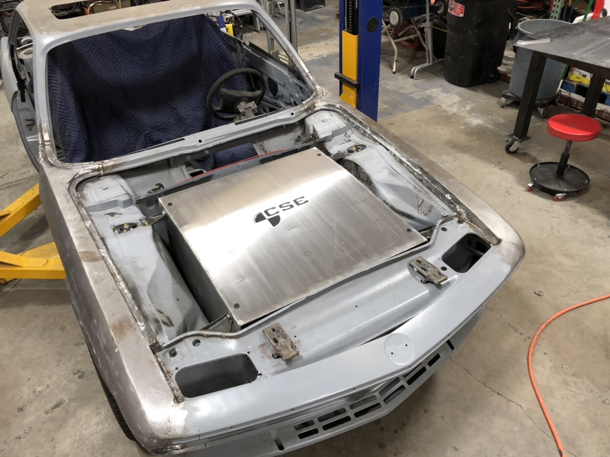
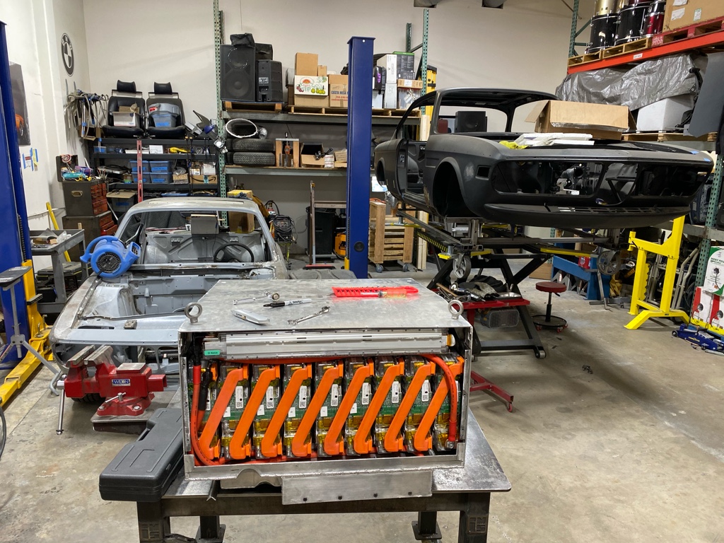
Now you can see our problem. We really need all this space for our Tesla battery modules. We needed to reconfigure things in a major way.
It all Started with Child Labor
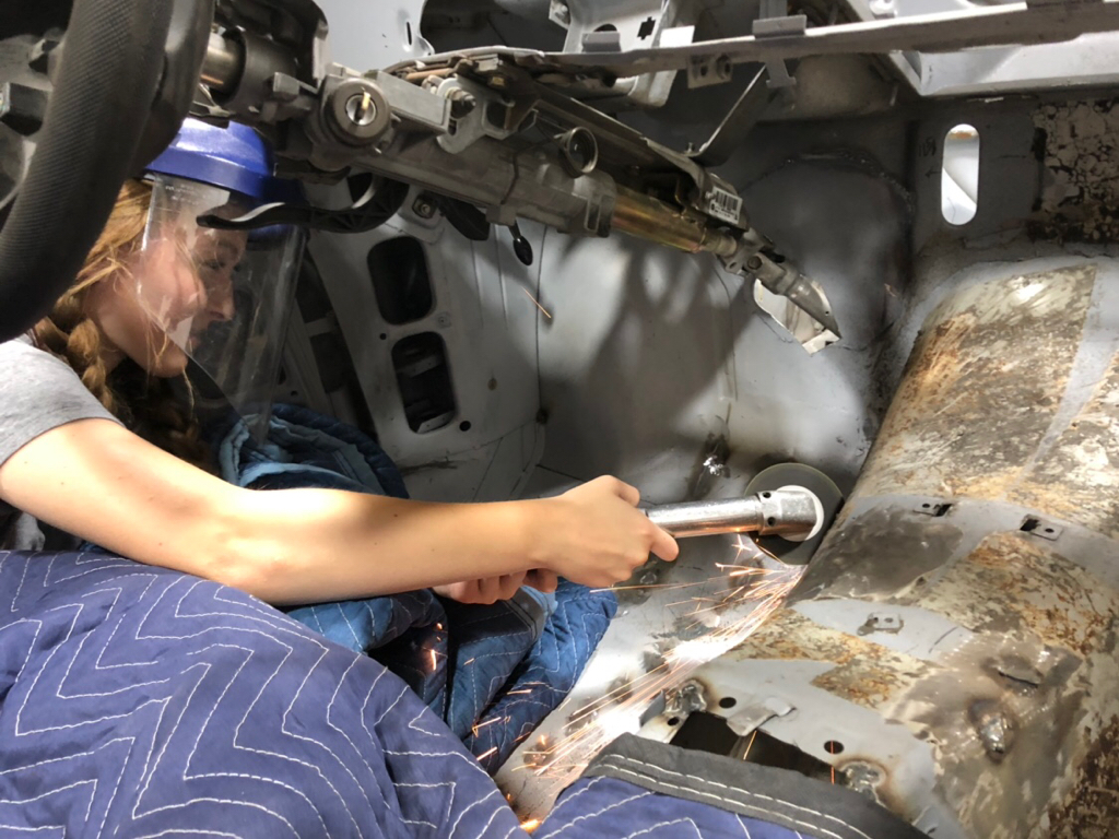
My daughter Maggie had been asking to help with the project so this was her perfect opportunity. There were no gloves small enough in the shop but I did have a face mask. She did a terrific job cutting away the steel!
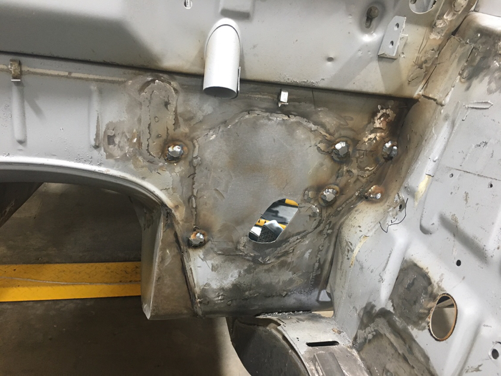
After the floor was cut out Tyler welded in some sections and smoothed it out.
Now we have a very comfortable space for both feet. I’ll go ahead and say it:
No more two left feet. (You’re welcome).
Now, Back to the Brakes
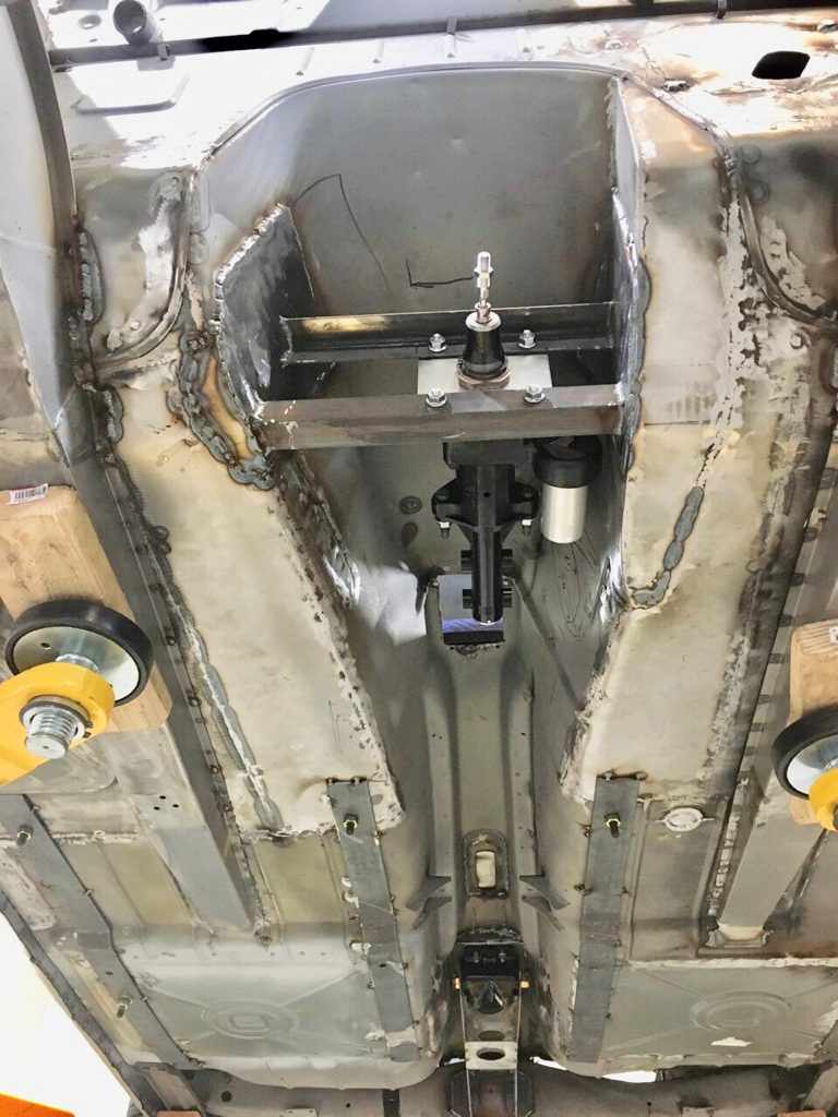
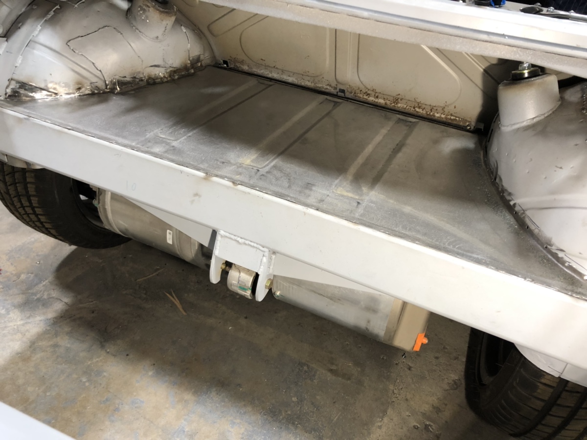
Since we have no transmission, we have no need for a
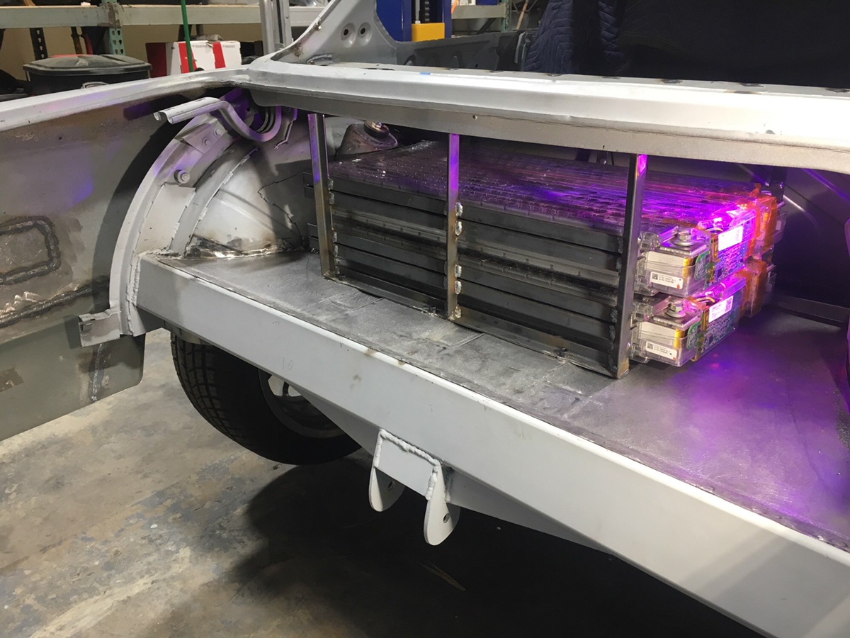
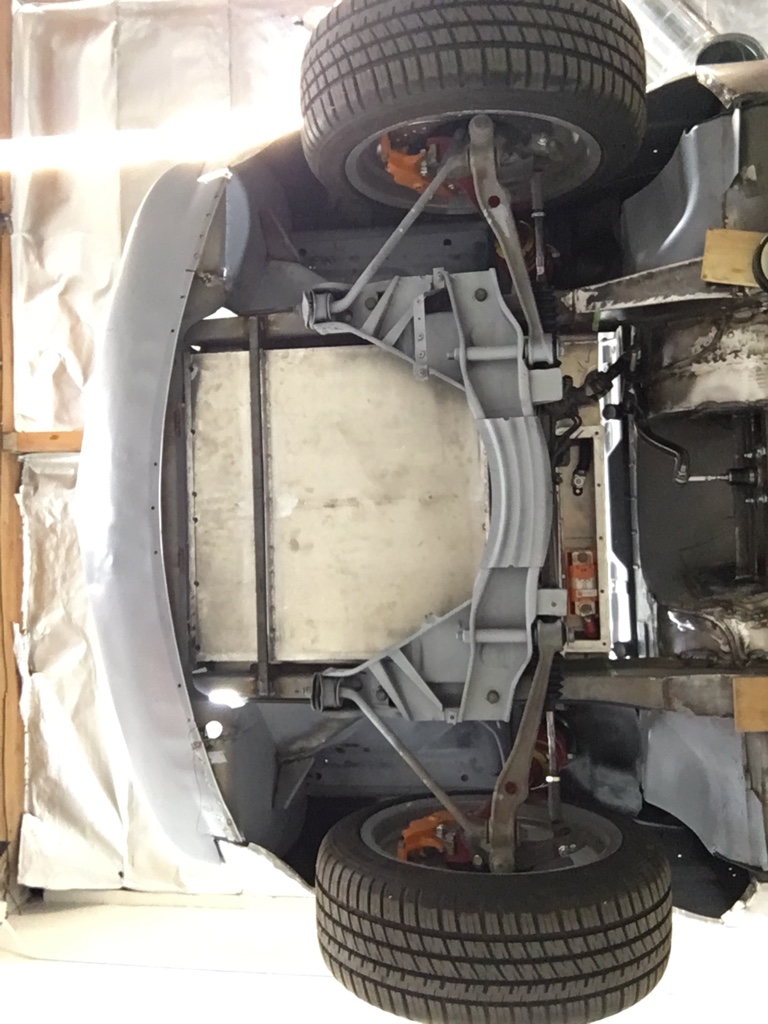
transmission tunnel. My idea is to install the brake booster here - backwards. We sourced a new Bosch Hydro-boost unit which will feed a new Wilwood master cylinder. Notice in the photo you can see where we took out some of the tunnel.
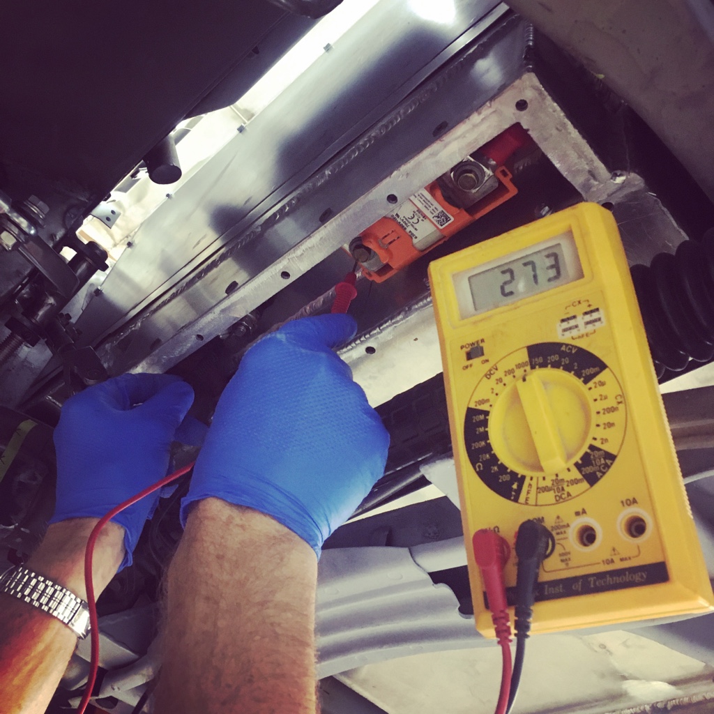
Another issue we have with the BMW brake booster is that it requires vacuum. We have no engine to provide us vacuum. We could install a vacuum pump, but it makes more sense to move to a hydro-boost style booster. With hydro-boost, the power comes from your power steering pump. Since we have a 12 volt power steering pump to power our steering rack anyway, this becomes a very elegant and unified solution. In the photo you can see the brake setup installed securely, backwards, into the tunnel.
Enter Greg
At this point we have one huge gap in the essentials of braking. Connecting the brake
pedal to the brake
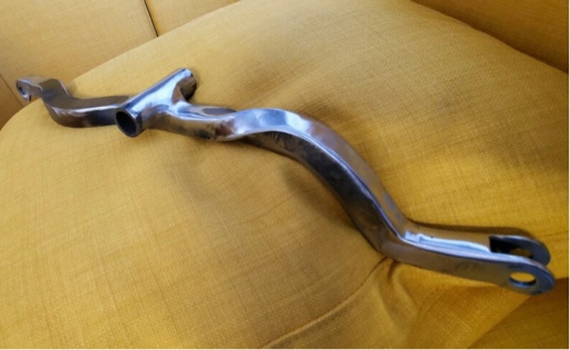
booster. This is where Greg comes in. My concept is to build a lever which will receive the rod from the brake pedal and invert that motion backwards into the booster. Essentially a brake teeter-totter. While I may have brought the idea, it was Brett that brough the magic. I kept calling our device a lever, but Brett didn’t see that as the correct term. He just decided to name it Greg.
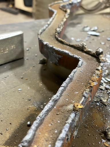
Brett started with a piece of 3/4” inch steel plate and a plasma torch. He had made a guide and could just ride the torch along for a perfect cut.
The plasma torch provides some terrific looking metal artifacts.
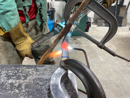
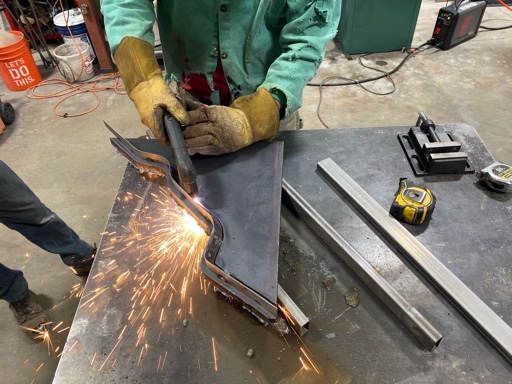
We heated Greg up a few hundred degrees where he gave up his strength and we could twist him into the compound shape we needed. Once the shape was achieved, we evenly heated Greg up to get his particles all in harmony for strength.
After the cutting, cleaning, twisting, heating was done Brett welded ends on it, and the pivot point. He attached a very strong receiver to the firewall and we now have a terrific braking solution which takes up less than 2 inches of the engine (battery) compartment.
Cheers,
Paul