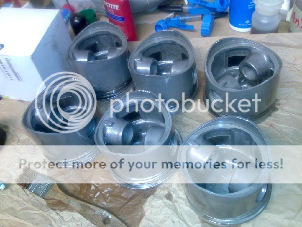
my new engine M30B30

important question

please help me with this, considering that is impossible to place two or three separators per valve, to accomodate a sharing of the stress around the valve circumference, and knowing that i can only place one 5mm nylon separator per valve,...do you think that i am on the risk of bending the valve rod ?

regards

 
Yes, I looked at your picture the other day and my immediate thought was just that, I think you would need at least 3 of these spacers per valve
 
Yes, I looked at your picture the other day and my immediate thought was just that, I think you would need at least 3 of these spacers per valve

i know, i know, three and just separate them 120degrees, but there is no space for all the three of them

my concern is that i do not know the force exerted by the spring, nor the effect of that static load on one side of the valve that will create torque in the rod

what to do ?...
 
Interesting idea, but the usual way to assemble a head is cam first, rockers/rockershaft second.

First you put in the cam with plenty of lub on the bearing surfaces.
Then put in the rocker shafts, assembling each rocker system in a row, all intake then all exhaust, rotating the cam so that the rocker being added is unloaded. You have to pound the rocker shafts with a soft mallet, but no other special tool is required.

The rocker shaft needs to be slightly out of place to add the retainer clips for each rocker, but all one shaft can be done a once.
 
start motor overhauling


once all the parts are ready i begin the reasembly,


i have regreased the main moving parts, but keeping the threads clean


using blue loctite, medium strength


done


Last edited:
pistons and rings

i will reuse the pistons, and place new rings, easy operation, but some care must be taken,

set of rings, these are the right ones for +0,25mm


place them in order, first one the bottom one, you will see it identified by the drawings in the plastic bag, this one is tricky, it is composed of two pieces, you must remove the inner one first


place it in the piston in one position, lets say "zero",


now the other piece, the outer one must be placed 180 degrees from these one:


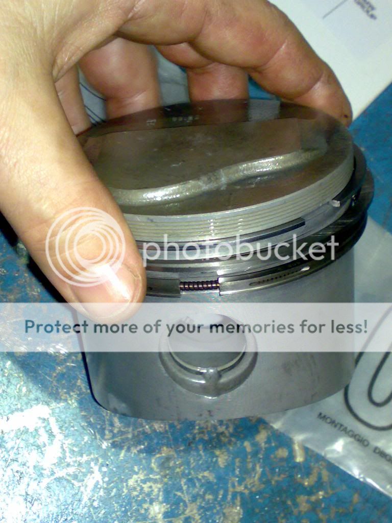
just take care of the upright position is where the letters TOP can be found:


first one is ok now:


second one, no special tip but to place the letters TOP correctly:


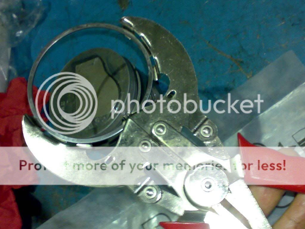
the third one needs a tool to place it


and you are done,


another five are waiting for you


remark: there are more mounting tips when these pistons go for the assembly in the block, as the rings had to be positioned in a certain direction
 
Last edited:
i cut the old head bolts to use them as guides for the rocker shafts


spring valves ready, used a tool but have no pics of the process, sorry


after springs are assembled, valves look awesome, compression checked with a vacuum meter

 
Great documentation and detail work as usual DQ. Looks like a very satisfying puzzle.
 
the PITA !!! never again !!

it was time to introduce the camshaft, so i prepared the head for it, a stable surface, my carpenter table with a wonderful opening in the middle, the head was over two thick long wood pieces to let the valves move freely, and i strongly fixed it with two vices to avoid tilting when using the screwdriver method


yes, i decided to try the screwdriver method as the haynes explains it, just pressing the valves to provide free space for the camshaft to pass through the rockers

starting was not a problem, here you can clearly see the two lateral 10mm thick long wood pieces, that avoid the valve heads hitting the table underneath when you press the springs sequentially
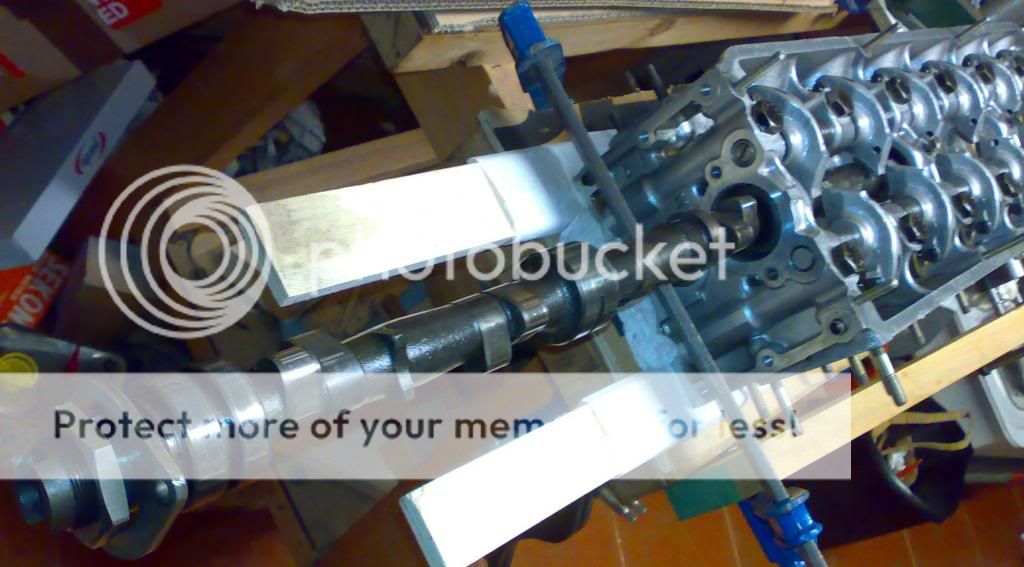


a view of the screwdrivers placed to press the springs: i used three of these as a basis, and an additonal one occasionally
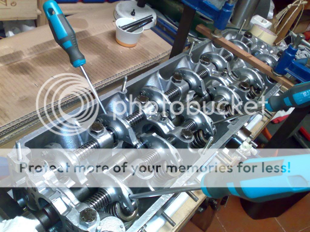


i used a steel plate that lays underneath the table to support the cables that fix the screwdrivers, an additonal problem was that as all the parts were covered with oil, you can imagine how slippery was the cable, so grabbing it was a real problem...


it is impossible to explain the process, you have to check the way in which the camshaft is going to move, and see the rockers that will provide obstacles to that movement, but the degrees of freedom of the system are really a lot, because you must take advantage of the lineal displacement of the rockers too, so there is not a unique solution


it is a pain to advance every centimeter, rotating, moving the rockers, tensioning one, then the other, placing more cable to support the screwdrivers, watching your face realising the big tension that is bending those screwdrivers,...

a pause for dinner, and when i returned it seemed easier,...


done,...yes, but, never again !!


i do not have 12 screwdrivers, but that would have been probably the solution,..., maybe for the next car,...who knows ?
 
Last edited:
help, a question on start motor

hello,

i would like to test my start motor but i am reluctant to fry it, so i prefer to ask, so provided this schematic drawing:


i assume that the ground (negative pole) comes through the motor case

i assume that the big thick positive cable goes to ref. 1

so, which is the positive signal coming from the starter ? going to, ref.2 or ref.3 ?

and assuming that, what pole do i have to connect to the other terminal (say the remaining between 2 and 3) ? a (+) or a (-) ?

thanks
 
Back
Top