The Raven e9 project

autokunst

Well-Known Member
Site Donor $$
Messages
3,607
Reaction score
2,620
Location
Milwaukee, WI
@autokunst @HB Chris
Thanks to Chris Macha for texting me, I'm not on this site daily. I have "pelly" pans, and I've read the forum discussions about how my front pans are preferred to W/N. I sold pans long before W/N, installing the first set on my coupe nearly 20 years ago (I still own that coupe). Over the years I've only had two complaints.... last month a buyer didn't like the amount of 'warp' (once they are welded into place, the warpage disappears). The second complaint was about a year ago when a customer reported my front pans didn't align with W/N rears. I wanted to disclose these issues because your the level of craftsmanship is top notch and I'm not sure my pans will solve your problem.
Hi Mike,
Thank you for replying, and thank you to @HB Chris for getting in contact with you.
I am interested in learning more (photos please). I'll send you a PM in hope of continuing this conversation. Frankly, I am not worried about some warps - all of these replacement panels have that and it is easy to shrink or stretch the panels once fit and welded. As for the rib alignment, I suspect no panel will "automatically" be perfect. But if your pans are wider (including more of the center section towards the tunnel) and have the stampings where the plugs go, I'm in! Talk soon.
 

autokunst

Well-Known Member
Site Donor $$
Messages
3,607
Reaction score
2,620
Location
Milwaukee, WI
Another small distraction today - you know I love distractions. :D 
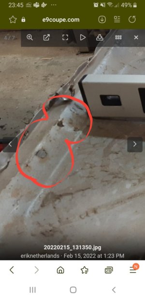
As I wait to connect with Mike Pelly for some front floor pans, I turned my attention to the rears. I will be using the WN rear panels and I can absolutely confirm the observations/experiences that @eriknetherlands reported regarding the WN rear pans having a front-to-back dimensional discrepancy. Measuring from the two welded/captured nuts to the front of the foot well, there is a solid 1cm difference (the WN dimension is shorter than the original). You wouldn't think this is a big deal, but the nuts need to be where they are, and the front of the footwell engages the rear of the frame rail - so this is a fixed dimension that needs to be maintained. I haven't decided what I'll do, but will likely push the WN panels forward to engage the frame rail snuggly, and then likely relocate the welded nuts as required in the back. The rear of the footwell is inconsequential, I think.

I started to cut out a large portion of the rear floor pan from the car. But I wanted a reference point for the rear suspension. So I needed to find my push rods (the blue book refers to these as "tie rods", but the orange parts book refers to them as "push rods". I think push rods is a better description). Once I found them in the correct bin, I decided to clean them up.
20220213-tie push rods.jpg


These poor, tortured pieces. I would guess - no, I would wager - that every one of these on an unrestored car has been the victim of an errant jack placement. It was evident that at some point over the past 49 years, both of mine had supported the weight of the car. After cleaning them up it was easy to see that they were slightly bent and had the marks from a metal jack pad. But they are as good as new now.
 
Last edited:

eriknetherlands

Moderator
Site Donor
Messages
2,753
Reaction score
1,993
Location
Netherlands, Eindhoven area
.....
The rear of the footwell is inconsequential, I think.

I started to cut out a large portion of the rear floor pan from the car. But I wanted a reference point for the rear suspension.
.....

Indeed the rear isn't important once you relocate the 2 m8 bolt holes.
(I should have done it like that as well)

Just a tip, hope it is not too late:
I marked the position of the m8 bolt holes, their center line, on the bottom flange of the inner sill. With a 90 degree angle I marked their position with a small 0,5 mm deep slit. Also measure the distance between the first bolt hole to the inner sill flange.

edit: pic added:
20150725_232559.jpg
20150725_232609.jpg

Then after reinstallation of the new floor panel, you can easily relocate the m8 holes relative to that line (slit) on the inner sill.
 
Last edited:

eriknetherlands

Moderator
Site Donor
Messages
2,753
Reaction score
1,993
Location
Netherlands, Eindhoven area
Updates and a QUESTION (below)

Here's the big question. Are the rear floor wells supposed to have this angled depression? Or should the well be relatively flat? Mine original floors are/were angled down, but they were also pretty corroded and had 45 years of people stepping on them, so I don't know. Thanks in advance.
View attachment 135849

I just measured the part that i chopped from my car. depending on which 'step' you measure it, I get:
- 19 mm when measuring left to right on the first step
20220215_131350.jpg
20220215_131410.jpg

and
- 33 mm; when measuring front to back on the second step

20220215_131448.jpg
20220215_131459.jpg
 

HonaloochieBoogie

Well-Known Member
Messages
326
Reaction score
363
Location
Port St Joe, Florida
Many would have reconditioned those pans. I only detect rust around the hole in the center. Shows the standard you are holding yourself to on this work. Better than new by a long shot.
 

eriknetherlands

Moderator
Site Donor
Messages
2,753
Reaction score
1,993
Location
Netherlands, Eindhoven area
Many would have reconditioned those pans. I only detect rust around the hole in the center. Shows the standard you are holding yourself to on this work. Better than new by a long shot.

It wouldn't be a bad thing if I kept them. It actually has two 2 cm rust holes. And some rust in the seam, which was my main target to get rid off
, but no holes in the seam. In hind sight it was quite salvageable, remove as I did, bead blast the open seam, weld up the holes, and put it back.
This one was the best, the other 3 were hopeless. It also the reason why I have not tossed it & it already has @Krzysztof on it.
 

Attachments

  • Screenshot_20220215-234608_Samsung Internet.jpg
    Screenshot_20220215-234608_Samsung Internet.jpg
    111.4 KB · Views: 92

autokunst

Well-Known Member
Site Donor $$
Messages
3,607
Reaction score
2,620
Location
Milwaukee, WI
With a larger portion of the rear floor removed, I was able to better assess the rear seat riser. First, I need to fill that speaker hole (at least I think it is a speaker hole). What a hack job. But the next decision I need to make is whether to replace / how much of the riser I replace. The front looks great! But portions of the inside along the bottom have some pitting. I will be dipping the car again which will thoroughly remove any oxidation - then the car will be electro-deposition coated. So I have to ask myself, do I need to replace every spec of pitting? There are certainly plenty of fully restored cars where the A-pillar is just cleaned up and coated - pitting and all. I don't think these pieces are available anywhere, so I would be making patches.
20220215-rt rear seat riser.jpg


A question I have is what the correct angle is for the rear seat flange. I have researched photos and it seems there is a gentle angle on this flange. Which is to say, not a 90 degree angle. But I think I may have too strong a rake currently. Does anyone have any data available? I also assume the top edge should be a straight line left to right. Mine needs a little hammer and dolly work.
20220215-rear seat riser flange.jpg
 

autokunst

Well-Known Member
Site Donor $$
Messages
3,607
Reaction score
2,620
Location
Milwaukee, WI
Last week when I asked the question "if" I should replace some pitting on the rear seat riser, I knew the answer before I posted the thread. YES, OF COURSE. Today I removed the small gusset piece that ties the rear seat riser to the inner sill. The reason I was leaving that gusset in place was because it was holding the sill plumb and precisely in place.

So before I removed it, I needed to brace the sill with a temporary piece.
20220220-temp sill brace 01.jpg

20220220-temp sill brace 02.jpg

20220220-temp sill brace 03.jpg


Some of you may recall that I found and refurbished a big, old resistance (spot) welder. It is awesome, but VERY heavy and TOO POWERFUL. Even on the lowest setting it reduces the metal to a molten splatter. I think I'll sell this one and find a smaller, more manageable unit.
20220220-really big spot welder.jpg


Here is the gusset still in the car.
20220220-inner sill gusset 01.jpg


And here it is on the bench. Much easier to work on. Looks great from the front, right?
20220220-inner sill gusset 02.jpg


And here is the back where the pitting is. I think I'll replace the metal up to the first rib.
20220220-inner sill gusset 03.jpg
 
Last edited:

Markos

Well-Known Member
Site Donor
Messages
13,369
Reaction score
7,502
Location
Seattle, WA
Last week when I asked the question "if" I should replace some pitting on the rear seat riser, I knew the answer before I posted the thread. YES, OF COURSE. Today I removed the small gusset piece that ties the rear seat riser to the inner sill. The reason I was leaving that gusset in place was because it was holding the sill plumb and precisely in place.

So before I removed it, I needed to brace the sill with a temporary piece.
View attachment 136562
View attachment 136563
View attachment 136564

Some of you may recall that I found and refurbished an big, old resistance (spot) welder. It is awesome, but VERY heavy and TOO POWERFUL. Even on the lowest setting it reduces the metal to a molten splatter. I think I'll sell this one and find a smaller, more manageable unit.
View attachment 136561

Here is the gusset still in the car.
View attachment 136558

And here it is on the bench. Much easier to work on. Looks great from the front, right?
View attachment 136559

And here is the back where the pitting is. I think I'll replace the metal up to the first rib.

Would not have replaced. That is dedication!
 

bluecoupe30!

Well-Known Member
Site Donor
Messages
2,146
Reaction score
1,294
Location
Delta, British Columbia, Canada
Looks great from the front, right?

Not difficult to find pitting on a 50 year old car after media blasting or dipping. Many manufacturers market rust neutralizing products that claim to arrest the process, if used correctly. Many of us are, ahem, in our 6th or 7th decade, so I wonder if something such as SEM Rust Mort, plus appropriate primer, then topcoat, may be useful in this type of situation. o_O
 

eriknetherlands

Moderator
Site Donor
Messages
2,753
Reaction score
1,993
Location
Netherlands, Eindhoven area
Dedication! I'd chop the rusted bit out as well, but you'd probably guessed that already...

Surely your car would drive and give you a great smile if you left the clean but pitted gusset in there.
But now you had some extra quality time in the garage!

Ps for your welder: you could consider making thinner copper arms: they will heat up more, cutting effective welding time ('cyle time'), but they'll also loose some power on the way. Not nice, but possibly effective.
Do I spot screw-on type tips on the copper arms? If so, it might even be an option to unscrew them, and put a 1 mm isolator in between. It'll get hot, but it may just cut the effectiveness of your welder enough to be satisfied.
 
Last edited:

autokunst

Well-Known Member
Site Donor $$
Messages
3,607
Reaction score
2,620
Location
Milwaukee, WI
Surely your car would drive and give you a great smile if you left the clean but pitted gusset in there.
Erik, I don't imagine you would leave this area pitted. ;) And I'm not sure I can sleep well at night knowing that I left some areas pitted while fixing so many other areas. The line is hard to draw. My goal is to be able to say unequivocally that the car is rust free. Not sure where "cleaned pitting" falls. I'll talk with the electrodeposition place to see if their process stops rust from returning in a pitted area. If yes, then perhaps I can lean out my process slightly.
 

mulberryworks

Mr. Fixity
Site Donor
Messages
1,244
Reaction score
614
Location
Jacksonville FL
Dedication! I'd chop the rusted bit out as well, but you'd probably guessed that already...

Surely your car would drive and give you a great smile if you left the clean but pitted gusset in there.
But now you had some extra quality time in the garage!

Ps for your welder: you could consider making thinner copper arms: they will heat up more, cutting effective welding time ('cyle time'), but they'll also loose some power on the way. Not nice, but possibly effective.
Do I spot screw-on type tips on the copper arms? If so, it might even be an option to unscrew them, and put a 1 mm isolator in between. It'll get hot, but it may just cut the effectiveness of your welder enough to be satisfied.
Have you tried running the welder on 120V instead of 240v? On the higher setting that may give you enough power for a good weld. It won't help with the large size of course. I have a TIG welding that runs on either voltage and so comes with a cord that has a 120v plug and a 220v socket, it shouldn't be too hard to find one. The TIG is designed to run on either voltage, 'cus modern electronics 'n stuff you know but 120v won't deliver quite as much amperage as 240v.
Your welder should provide exactly half the power on half the voltage.
 

autokunst

Well-Known Member
Site Donor $$
Messages
3,607
Reaction score
2,620
Location
Milwaukee, WI
Have you tried running the welder on 120V instead of 240v? On the higher setting that may give you enough power for a good weld. It won't help with the large size of course. I have a TIG welding that runs on either voltage and so comes with a cord that has a 120v plug and a 220v socket, it shouldn't be too hard to find one. The TIG is designed to run on either voltage, 'cus modern electronics 'n stuff you know but 120v won't deliver quite as much amperage as 240v.
Your welder should provide exactly half the power on half the voltage.
Interesting idea. This Miller LectroSpot welder is NOT modern electronics. It has vacuum tubes!!! I can certainly try it on 120v - not sure how the tube circuit will respond to that (I think it is the timer circuit). You're right, it will not do anything for the weight. This thing is heavy.
WS.jpg
 

autokunst

Well-Known Member
Site Donor $$
Messages
3,607
Reaction score
2,620
Location
Milwaukee, WI
Have you tried running the welder on 120V instead of 240v? On the higher setting that may give you enough power for a good weld. It won't help with the large size of course. I have a TIG welding that runs on either voltage and so comes with a cord that has a 120v plug and a 220v socket, it shouldn't be too hard to find one. The TIG is designed to run on either voltage, 'cus modern electronics 'n stuff you know but 120v won't deliver quite as much amperage as 240v.
Your welder should provide exactly half the power on half the voltage.
Ian,
I spent $30 on this welder power adaptor cable. Unfortunately, my suspicion was founded. It turns out the welder will not weld at all at the lower voltage. The circuitry in this relic is pretty basic, but the timer/actuator circuit evidently needs the anticipated voltage to function. I'll be listing this beast on eBay.
20220226-220v to 110v.jpg
 

mulberryworks

Mr. Fixity
Site Donor
Messages
1,244
Reaction score
614
Location
Jacksonville FL
Ian,
I spent $30 on this welder power adaptor cable. Unfortunately, my suspicion was founded. It turns out the welder will not weld at all at the lower voltage. The circuitry in this relic is pretty basic, but the timer/actuator circuit evidently needs the anticipated voltage to function. I'll be listing this beast on eBay.
Sorry to hear that. Yes, new hardware can be voltage agnostic because they are designed to slice and dice the power available to get what the unit needs, a nice trick that only recently became affordable and almost ubiquitous. Spot welders like the ones I used in Jr. High shop class had no electronics at all, just a finger on the trigger to control the weld times so would be able to be adjusted with a Variac to operate on less than design voltage seeing as they are basically a big power transformer.
Yours lies in between these extremes and is locked into its design voltage due to its timing circuit.
I'm sure you'll be able to find it a new home.
 

autokunst

Well-Known Member
Site Donor $$
Messages
3,607
Reaction score
2,620
Location
Milwaukee, WI
Quick update - two topics. I am waiting for sheet metal, so I am trying to direct my energy elsewhere this week.

The spot welder:
First, I have to say that I always learn something on this forum. That may be my favorite part about this group. Sometimes I learn something from someone else, other times I learn something about myself. In this instance, both occurred. I realized that I was about to throw the baby out with the bath water. I'd invested time in this old, industrial strength welder - but not much research into learning how to set it up properly. Honestly, I assumed it was a pretty dumb tool - you plug it in, squeeze the handle, and bam - a good weld. But it turns out that's not entirely true. I did a deep dive on the science and technique of this tool, and then spent some time tuning it up. First, I dressed the tips much nicer and actually differently than I had previously. I also adjusted the tension. Increasing the tension changes/lowers the resistance between the copper and steel and transfers the heat to the lower resistance steel-to-steel connection - AKA, the "nugget". I did a few test welds and the results were so much better. These welds will hold very well.

Dressed tips.
20220227-dressed tips.jpg


Test welds. The first attempt (marked 1) still had a bit of expelling (splatter), but the other three were cleaner. Well, number 3 did get a bit liquid on the top surface, too. Regardless, I am encouraged. These are much closer to the original joints than my previous tests. Attempts 1 through 3 were done for 10 cycles, the fourth was done for 20 cycles. The timer circuit measures its time in cycles of AC current. At 60 Hz (cycles per second) 10 is 1/6 of a second - and 20 is 1/3 of a second.
20220227-top.jpg

20220227-welds btm.jpg


Tying up loose ends (pun intended):
I had lost sight of my bench surface as projects I've started remained sitting on the bench. So I set out to clean the bench, and in doing so finished up a portion of the project, too. I had purchased new Lemforder tie rod ends, and a replacement center track rod. The new parts were good in that they functioned well and the ball joints moved freely. However, I didn't care for the paint finish on them - it was already flaking or scratching off. So I cleaned them up and refinished them. In this re-painted state, the loose parts sat on the bench taking up far too much space. So I assembled the pieces back into assemblies, and pre-set the tie rods to match what came off the car. With EVERYTHING being replaced, I doubt the pre-set will even matter. But it gives me a place to start. The "old" center track rod on the car still had its BMW parts sticker. Which is to say, it had been replaced by a former owner. But the joints were tight and not rotating. I tried cleaning and freeing them, but there seems to be too much corrosion in the joints. Needed to go with new parts for smooth, accurate steering.
20220227-track and tie rods.jpg
 
Last edited:

HB Chris

Well-Known Member
Site Donor $$
Messages
19,418
Reaction score
8,759
Location
Huntington Beach, CA
And Stephen taught us something new today as we spoke earlier. The original tie-rod nuts have split lock washers under them, the new ones have no washers of any kind. I had both at hand to check.
 

autokunst

Well-Known Member
Site Donor $$
Messages
3,607
Reaction score
2,620
Location
Milwaukee, WI
And Stephen taught us something new today as we spoke earlier. The original tie-rod nuts have split lock washers under them, the new ones have no washers of any kind. I had both at hand to check.
Ah, but now what do we do? Add a split lock washer to the new parts? Keep no locking washer (seems risky). Maybe just use some blue loctite?

UPDATE - the new bolts that come with these are shorter than the old parts. I don't think there's enough thread length to add the washers (admittedly I haven't torqued mine yet). But I do like the blue loctite option with this in mind.
 
Last edited:
Top