The Raven e9 project

Almost forgot another topic. I also removed the rear seat riser and left side gusset. This will make patching the speaker holes and any corrosion patches much easier and better. This assembly of three pieces (riser and gussets on each side) appear to provide some bracing/stability to the inner sill and B-pillar. But the sheet metal is thin and is not attached very robustly. In fact, there are two factory mig welds at the top of the tunnel to the riser, and one of mine had cracked, the other showed stress.

I don't want to add much weight, but I wonder if making a tube brace of some sort would add noticeable stiffness to the chassis. This would be entirely behind the sheet metal pieces and would not be visible in the car (unless you removed the rear seat). I am showing two versions in the following sketch. A third would be to tie this assembly back to the chassis points. Thoughts?

20220226-riser bracking diagram.jpg
 
Personally I wouldn’t add bracing, but as you have to repair all the pieces anyway is there any mileage in considering remaking everything in thicker gauge steel and welding it in more thoroughly?
 
I thought about a similar thing while working on it. Didn't make any mods there is myself, but I seriously considered a horizontal brace, tucked under the top edge. I've seen it in another members car here on the forum btw.

Wrt forces in those area's, 2 things that I have noticed in various e9's:

I have seen some cars with cracks in the floor at the front edge of the diff mount reinforcement plate under the car. It is basically where the drive shaft tunnel ends when looking front to back.

Secondly you mention that one of the mig welds failed. I can only think of a mechanism for that failure when one rear wheel pushes a corner up. If then the sill bends up ever so slightly ( remember it will always bend a bit, we just may not see it happening), the seat riser and its 2 migs welds will shift left to right and back relative to the floor. To counter act this, you'd need a triangle in the vertical field from the rear wheel arch to ( roughly) the failed mig point. But that is cutting it right through your seat buckets. Limiting that left-right shift therefore only seems doable by making a horizontal connection from the failed mig point on top of the tunnel with the rear chassis corners, the large pins; is that low enough to clear the underside of the seat buckets? Your concept B will also help to limit this left-right movement.

On the other hand, the failed diff mounts in that area are probably due to rotation forces of the differential. That piece of floor would also benefit from some reinforcement, especially if you drive the car spirited. Annoyingly, again here going vertical is what you need, but the seat buckets are again in the way; I think there is little or no space to be found to fit a tube from that front end point of the diff reinforcement plate to the curved section making the rear wheel arches, roughly where the upper belt mount points are.
Could you tie them in to the sill at the b-pillar; another triangle roughly in the horizontal plane? Basically, taking option B, but adding a diagonal from the failed mig po oint to the chassis points (thick vertical pin )?

Hope my words help a bit. Currently skiing, so no access to easy sketching tools on my phone....
 
Personally I wouldn’t add bracing, but as you have to repair all the pieces anyway is there any mileage in considering remaking everything in thicker gauge steel and welding it in more thoroughly?
I think this is a solid approach - the engineers must have crunched some numbers back then. These pieces are probably more complex than I can handle (in a reasonable amount of time). But I can look for areas to reinforce the sheet metal.

I thought about a similar thing while working on it. Didn't make any mods there is myself, but I seriously considered a horizontal brace, tucked under the top edge. I've seen it in another members car here on the forum btw.

Wrt forces in those area's, 2 things that I have noticed in various e9's:

I have seen some cars with cracks in the floor at the front edge of the diff mount reinforcement plate under the car. It is basically where the drive shaft tunnel ends when looking front to back.

Secondly you mention that one of the mig welds failed. I can only think of a mechanism for that failure when one rear wheel pushes a corner up. If then the sill bends up ever so slightly ( remember it will always bend a bit, we just may not see it happening), the seat riser and its 2 migs welds will shift left to right and back relative to the floor. To counter act this, you'd need a triangle in the vertical field from the rear wheel arch to ( roughly) the failed mig point. But that is cutting it right through your seat buckets. Limiting that left-right shift therefore only seems doable by making a horizontal connection from the failed mig point on top of the tunnel with the rear chassis corners, the large pins; is that low enough to clear the underside of the seat buckets? Your concept B will also help to limit this left-right movement.

On the other hand, the failed diff mounts in that area are probably due to rotation forces of the differential. That piece of floor would also benefit from some reinforcement, especially if you drive the car spirited. Annoyingly, again here going vertical is what you need, but the seat buckets are again in the way; I think there is little or no space to be found to fit a tube from that front end point of the diff reinforcement plate to the curved section making the rear wheel arches, roughly where the upper belt mount points are.
Could you tie them in to the sill at the b-pillar; another triangle roughly in the horizontal plane? Basically, taking option B, but adding a diagonal from the failed mig po oint to the chassis points (thick vertical pin )?

Hope my words help a bit. Currently skiing, so no access to easy sketching tools on my phone....
I am half following. I probably need to look at the car and read your words again. And I should also pull my rear seats down from the shelf to make sure I don't create a conflict. I do like the idea of getting some diagonal reinforcement between these critical force points.

By the way, here's a photo of the broken weld and stress crack. Honestly, it is a pretty tenuous connection.
20220226-stress cracks.jpg
 
Work has increased at the office, making it hard to get out to the garage. Last week was tough, next week will be more challenging. But today I was able to test out the press form I made for the rear seat riser middle panels. I can tweak my setup to get it a little better, but I am pretty happy with this.
20220306-01 press setup.jpg
20220306-02 still in jig.jpg
20220306-03 comparison.jpg


One of the biggest aspects of this test was to see if using MDF would be adequate for the female portion of the form. It was - I reinforced the edges with cyanoacrylate. I still used steel for the male press form. This will inform how I make forms for other areas (like the plug bosses in the floor pans).
 
That is impressive. How did you cut the steel male press form? Looks pretty thick with a very clean cut.
 
That is impressive. How did you cut the steel male press form? Looks pretty thick with a very clean cut.
For that part I used a cold saw for the straight cuts (chop saw but spins at a lower rpm made for metal). This saw does leave an exceptionally clean cut. For the corners I rough cut them with a cutoff wheel and then finessed to my line with an air file (hand held 1/2" wide belt sander). I'm finding that metalwork has a lot of art involved in the process. I see guys that can get super precise and clean cuts with die grinder and cutoff wheel. Me, I usually need to leave a line and sneak up to it with a finer grained tool.
 
Day 699
474.50 hours


I'd taken about 7 weeks off of working on the car to focus on a house project. But with that behind us, I've been able to get back at it. It was tough going to work every day and seeing the shop calling my name longingly.
20220617-the shop is calling.jpg


Getting back into it - gratuitous flying sparks shot.
20220606-gratuitious spark shot.jpg


Before the hiatus, I'd just started on the right side floor but was waiting for a response from a forum member that never came. While waiting I started a distraction by working on the rear sear riser pieces. Happy to say that those pieces are now finished and ready to be reinstalled when the floors are complete.
20220618-seat riser complete.jpg


I have been going back and forth between mig and tig welding. I feel the gold standard for welding thin sheet metal is tig, but I am still developing my thin metal skills. I feel that these inner pieces - parts that will generally never be seen in broad view - give me the opportunity to build my tig skills on thin sheet. These are 20 gauge (approximately 0.9mm thick). I am very pleased with the bead profile and minimal heat signature. This joint was pretty easily ground and planished out. By the time I am doing outer body panels, I hope I'll be even more comfortable with these thin metal welds.
20220618-getting better at tig on thin.jpg


Getting back to the floors, I started to fit the right rear patch piece. As noted by @eriknetherlands and others, the WN panel has some flaws. For me, two out of three of the beads at the rear aligned. The inner one is off by a few mm. Enough to bother me, but not enough to re-work the whole rib. I will probably jog the rib over a bit and try to blend them in without doing major surgery.
20220618-floor 1.jpg

20220618-slight misalignment.jpg


The bigger problem is that rear foot well is not the correct size. One has to choose whether to align the back of the footwell, which also places the welded tie rod nuts in the correct place - OR - align the front of the footwell which fits the well with the back of the frame rail more tightly. The latter/forward position requires reworking the tie rod nuts.
20220618-rear pan alignment 1.jpg
20220618-rear pan alignment 2.jpg


When I left the garage this afternoon I was leaning towards aligning at the rear and just dealing with the 15mm gap at the back of the frame rail. But as I type this, I wonder if the better move is to reposition the nuts so the frame rail gap can be closed up. I welcome input.
 
I have the gap at the frame rails, and kick myself over it every time i see it.

I would definitely reposition the 2 M8 nuts and their corresponding holes next time I would be confronted with it.
This is what I wanted/needed to hear. I will re-layout the pan in the forward position to verify the fitment and relation to other connection details. Thanks for the input!
 
This is what I wanted/needed to hear. I will re-layout the pan in the forward position to verify the fitment and relation to other connection details. Thanks for the input!
Isn't it great when you’re tormenting yourself about whether to you should go through a bunch of extra work to fix something versus just putting it in the "no one will ever see it but me" category, and then someone who actually went through the same dilemma offers a clear "Looking back I really wish I had done it right"? Somehow it actually makes the extra work quite a bit less painful because you are now sure it's the right decision.
 
Last edited:
@Bmachine , you know that my goal is generally always to "do it right". But I think that metric is on a sliding scale. In this case, "right" would be getting or making a better floor pan - one where the foot well has the correct geometry. But I'll sacrifice that for this minor relocation of the thrust rod attachment. That is easy in comparison. No complaints.
 
Lots of distractions here. Work has been busy, and I've had some health hurdles. And of course, there is the new '02 that I spent 6 or 7 weeks refreshing (and driving). But I am finally getting back at it on The Raven. I left off having just started to weld in the right rear floor panel. I finished most of that up and have started fabricating the front panel.

The piece you get from WN has a decent well, but it is missing any/all ribs and the flange that welds to the inner sill. Also missing are any pressings and holes for the access points into the frame rails. As of this morning, I have three of four ribs rolled in. Special thanks to a forum member - I think it was Ian @mulberryworks - who suggested that the ribs will drift if they are all marked at once. I am pre-stretching the metal before rolling the beads and that is helping a lot. But by the fourth bead, I did notice about a 1.5mm migration of my initial layout line. Fortunately, I measured and rolled each bead one at a time. Rolling the front up to meet with the bulkhead was fun - that started making it real. Now I just need to make some press forms for the access holes.

I wanted to wait before posting until I had these parts installed. But if I post, it helps me build momentum. Here are some progress pics.
20221105-new beads.jpg
20221106-rolling front edge.jpg
 
Well, a b34 would have been Motronic 1.0 with the Dizzy on the front of the head. It could have been converted back. And 82 was the first year of the improved b30 head with smaller water passages vs. the peanut shaped passages which would make sense, at least to me. I think the piano tops would be 9:1 compression, US got 8:1, rest of world 9:1.

First year Motronic, if I am not mistaken, was on the, 81 635 M90s and one year only. I pretty much am sure I am correct from the research I did regarding my Euro 635 which was original when I bought it right down to all brackets and original nuts and bolts
 
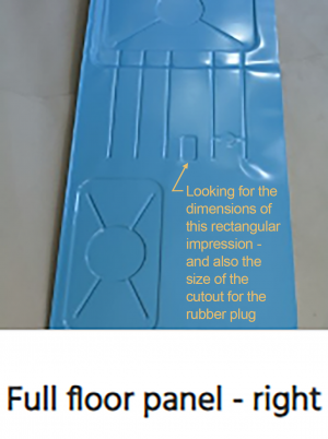
HELP! I am hoping someone can provide me with the dimensions of the rectangular pressing on the right side floor panel. The replacement metal does not have this and I can't find my original piece of this small area. Ideally, I'd like the x and y dims, and the approximate radius of the corners. Also, it would be helpful to know the size of the actual hole that the rubber plug fits in (assuming I can source a rubber plug of the same size or find my original). Thanks in advance!

Photo borrowed from the polish sheet metal company (that doesn't seem to be active anymore?).
rectangular impression.png
 
Back
Top